pool, spa or hot tub structure and to all electrical
components and equipment associated with the
pool/spa water circulation system.
2. The bonding must be accomplished by using a
solid copper conductro, No. 8 AWG or larger.
In Canada No. 6 AWG or larger must be used.
Bond the motor using the external bonding lug
provided on the motor frame.
To avoid the risk of property damage, severe
personal injury, and/or death, always disconnect
the power source before working on a motor or its
connected load.
WARNING
To avoid the risk of property damage, severe per-
sonal injury, and/or death, make sure that the con-
trol switch or time clock is installed in an accessible
locationsothatintheeventofanequipmentfailure
oralooseplumbingttingtheequipmentcanbe
turned off. This location must not be in the same
areaasthepoolpump,lter,andotherequipment.
WARNING
The pump must be permanently connected to a
dedicatedelectricalcircuit.Nootherequipment,
lights, appliances or outlets may be connected to
the pump circuit, with the exception of devices that
mayberequiredtooperatesimultaneouslywiththe
pump, such as a chlorinating device or heater.
WARNING
3.2.3 Electrical Wiring
To avoid risk of property damage, severe personal
injury, or death, always ground before connecting to
an electrical power supply.
WARNING
1. The pump motor must be securely and
adequately grounded using the green screw
provided. Ground before attempting to connect
to an electrical power supply. Do not ground to
a gas supply line.
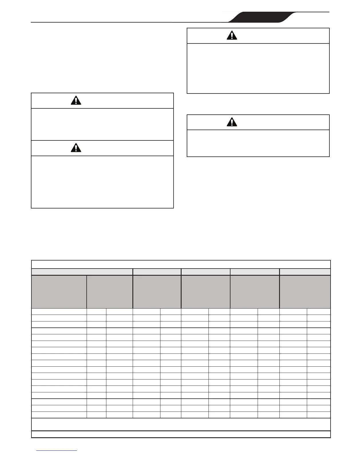
2. Wire size must be adequate to minimize voltage
drop during the start-up and operation of the
pump. See Table 2 for recommended wire sizes.
RECOMMENDED MINIMUM WIRE SIZE FOR SHP PUMPS*
Distance from Sub-Panel 0-50 Feet 50-100 Feet 100-150 Feet 150-200 Feet
Pump Model
Inverse - Time Circuit
Breaker or Branch
Fuse AMPs
Class: CC, G, H, J, K,
RK, or T
Voltage Voltage Voltage Voltage
230VAC 115VAC 208-230 VAC 115 VAC 208-230 VAC 115 VAC 208-230 VAC 115 VAC 208-230 VAC 115 VAC
SHPF .50HP/SHPM .75HP 15A 15A 14 12 12 8 10 6 8
6
SHPF .75HP/SHPM 1.0HP 15A 15A 14 12 12 8 10 6 8 6
SHPF 1.0HP/SHPM 1.5HP 15A 20A 12 10 10 8 8 6 6 4
SHPF 1.0-3PH 15A N/A 14 N/A 12 N/A 10 N/A 8 N/A
SHPF 1.5HP/SHPM 2.0HP 15A N/A 12 N/A 10 N/A 8 N/A 6 N/A
SHPF 1.5-3PH 15A N/A 12 N/A 10 N/A 8 N/A 6 N/A
SHPF 2.0HP/SHPM 2.5HP 15A N/A 12 N/A 8 N/A 6 N/A 6 N/A
SHPF 2.0-3PH 15A N/A 12 N/A 10 N/A 8 N/A 6 N/A
SHPF 3.0HP 20A N/A 10 N/A 8 N/A 6 N/A 4 N/A
SHPF 3.0-3PH 15A N/A 12 N/A 8 N/A 6 N/A 6 N/A
SHPF 5.0 25A N/A 10 N/A 8 N/A 6 N/A 6 N/A
SHPF1.0HP-2-SPD(1) 15A N/A 12 N/A 10 N/A 8 N/A 6 N/A
SHPF1.5HP-2-SPD(1) 15A N/A 12 N/A 10 N/A 8 N/A 6 N/A
SHPF2.0HP-2-SPD(1) 15A N/A 12 N/A 8 N/A 6 N/A 6 N/A
SHPM1.5HP-2-SPD(1) 15A N/A 12 N/A 10 N/A 8 N/A 6
N/A
SHPM2.0HP-2-SPD(1) 15A N/A 12 N/A 10 N/A 8 N/A 6 N/A
SHPM2.5HP-2-SPD(1) 15A N/A 12 N/A 8 N/A 6 N/A 6 N/A
*Assumesthree(3)copperconductorsinaburiedconduitand3%maximumvoltagelossinbranchcircuit.AllNationalElectricalCode
®
(NEC
®
)andlocalcodes
must be followed. Table shows minimum wire size and branch fuse recommendations for a typical installation per NEC.
(1)Two-speedpumpsarenotratedforusewith208VAC.
Table 2. Recommended Minimum Wire Size
Page 9
ENGLISH
Jandy
®
Pro Series Stealth
™
Pumps
|
Operation Manual