Page 13
ENGLISH
Jandy
®
VS FloPro™ Variable-Speed Pumps
|
Installation & Operation Manual
WARNING
ELECTRICAL SHOCK HAZARD
Turn off all switches and the main breaker in the variable-
speed pump electrical circuit, and allow five (5) minutes,
before starting the procedure. Failure to comply may cause
a shock hazard resulting in severe personal injury or death.
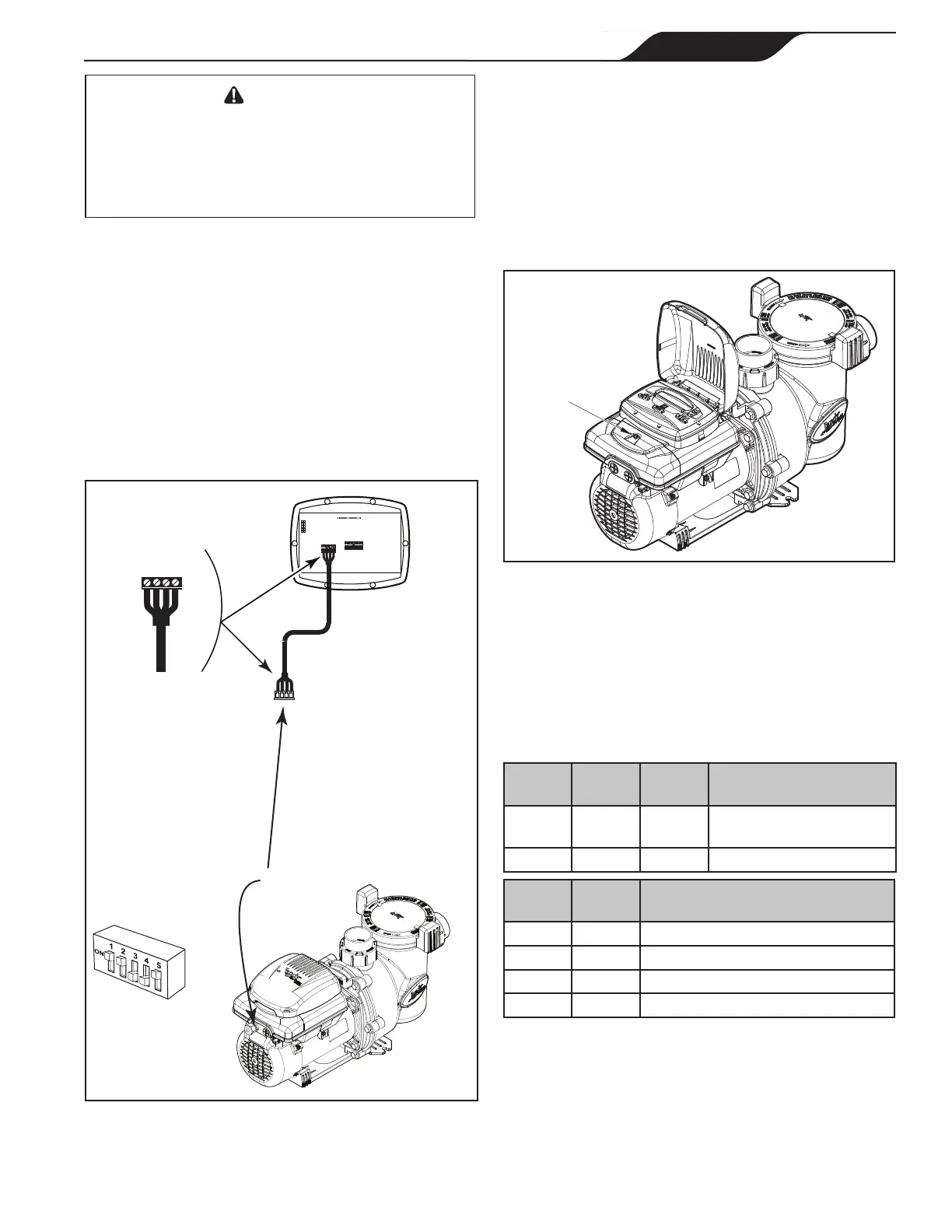
2. Remove the cover of the junction box and feed the
RS-485 cable into the tting.
3. Unplug the RS-485 connector.
4. Attach the four (4) wires in the RS-485 cable to
the RS-485 connector. Match the wire colors with
the positions on the connector: 1- red, 2- black, 3-
yellow, and 4- green. See Figure 9.
5.
Insert the RS-485 connector back into the pump.
6. Slide DIP switches 1 and 2 up, so they are in the
ON position, and slide switches 3 and 4 down, so
they are in the OFF position. See Figure 9.
BLACK
YELLOW
RED
GREEN
RS485
4321
RED
BLACK
YELLOW
GREEN
REMOTE CONTROL
54321
INPUT 2
INPUT 3
INPUT 4
COMMON
INPUT 1
Variable-Speed
Pump
Controller
(Rear View)
RS485
Cable (22 AWG)
5-Position
DIP Switch
Product may differ from images shown
Power Wiring
Port
Figure 9. Wiring Variable-Speed Controller (JEP-R)
7. Connect the other end of the cable to the controller.
Match the colors of the wires with the appropriate
connector positions as follows: 1- red, 2- black, 3-
yellow, and 4- green.
8. Secure wiring access cover to the pump motor.
9. Restore power to the pump and verify the operation
of the controller.
10. Refer to the Variable-Speed Controller Owner’s
Manual, H0412200, to operate the pump.
Remove to
access
DIP switch
Figure 10. DIP Switch Access Cover
3.3 VS FloPro Pump DIP Switch Settings
The 5-position DIP switch is located at the rear of the VS
FloPro pump. This DIP switch serves two (2) functions:
it selects the pump address, and it determines what type
of controller will be used with the pump.
Table 4. 5-Position DIP Switch Settings
Switch
1
Switch
2
Switch
5
Controller
OFF OFF ON AquaLink RS, AquaLink
PDA, or AquaLink Z4™
ON ON ON JEP-R and iQPUMP01
Switch
3
Switch
4
Pump Address
OFF OFF PUMP 1
ON OFF PUMP 2
OFF ON PUMP 3
ON ON PUMP 4
 Loading...