Page 10
ENGLISH
Jandy
®
Pro Series VS PlusHP Pumps
|
Installation & Operation Manual
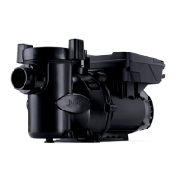
6. Connect the other end of the cable to an RS-485
connector on the AquaLink RS (or multiplexer
interface board), matching wire colors with
connector positions See “Figure 5. Wiring
AquaLink RS, PDA or Z4”
7. Restore power to the pump and verify the
operation of the controller.
8. Refer to the appropriate manual for set up and
operation of the pump:
• AquaLink RS Manual #6593
• AquaLink PDA Manual #H0572300
• AquaLink Z4 Manual #H0386600.
Variable-Speed
Pump
4321
RED
BLACK
YELLOW
GREEN
RS485
Cable (22 AWG)
BLACK
YELLOW
RED
GREEN
Connect to AquaLink RS RS-485 Connector
(or Multiplexer Interface Board)
S1
S2
RESET
SERVICE
TIME OUT
FILTER PUMP
AUX 1
AUX 2
AUX 3
AUX 4
AUX 5
AUX 6
AUX 7
RS6 & RS8 ONLY
RS8 ONLY
HEATER
SOLAR
POOL MODE
SPA MODE
SPA DRAIN
SPA FILL
AUTO
654321
10 9876 54321
4321
4321
4-Position
DIP Switch
4321
BLACK
YELLOW
RED
GREEN
Figure 5. Wiring AquaLink RS, PDA or Z4
3.2.4.2 Install with JEP-R variable-speed
controller
IMPORTANT
The installer must TURN ON switches 1 and 2 at the
VS-FHP2.0 pump when connected to the variable-
speed controller.
1. Disconnect the high voltage lines or open any
breaker to which the pump power is connected.
WARNING
ELECTRICAL SHOCK HAZARD
Turn off all switches and the main breaker in
the variable-speed pump electrical circuit before
starting the procedure. Failure to comply may
cause a shock hazard resulting in severe personal
injury or death.
2. Remove the junction box cover and feed the
RS-485 cable into the tting.
3. Unplug the RS-485 connector.
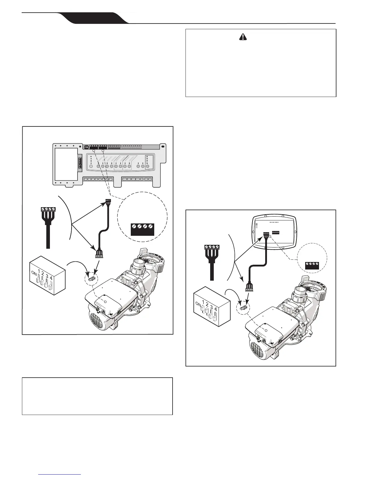
4. Attach the four (4) RS-485 cable wires to the
RS-485 connector. Match the wire colors with the
positions on the connector: See “Figure 6. Wiring
JEP-R VSP Controller”
5. Insert the RS-485 connector back into the junction
box.
6. Dip switches 1 and 2 must be in the ON position,
and switches 3 and 4 must be in the OFF position.
See “Figure 6. Wiring JEP-R VSP Controller”
BLACK
YELLOW
RED
GREEN
RS485
4321
RED
BLACK
YELLOW
GREEN
REMOTE CONTROL
54321
INPUT 2
INPUT 3
INPUT 4
COMMON
INPUT 1
4-Position
DIP Switch
Variable-Speed
Pump
Controller
(Rear View)
RS485
Cable (22 AWG)
4321
BLACK
YELLOW
RED
GREEN
Figure 6. Wiring JEP-R VSP Controller
7. Connect the other end of the cable to the
controller. Match the colors of the wires with the
appropriate connector positions. See “Figure 6.
Wiring JEP-R VSP Controller”
8. Restore power and verify the operation of the
controller.
9. Refer to the Variable-Speed Controller Owner’s
Manual, H0412200, to operate the pump.