22
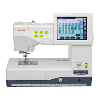
MC350E
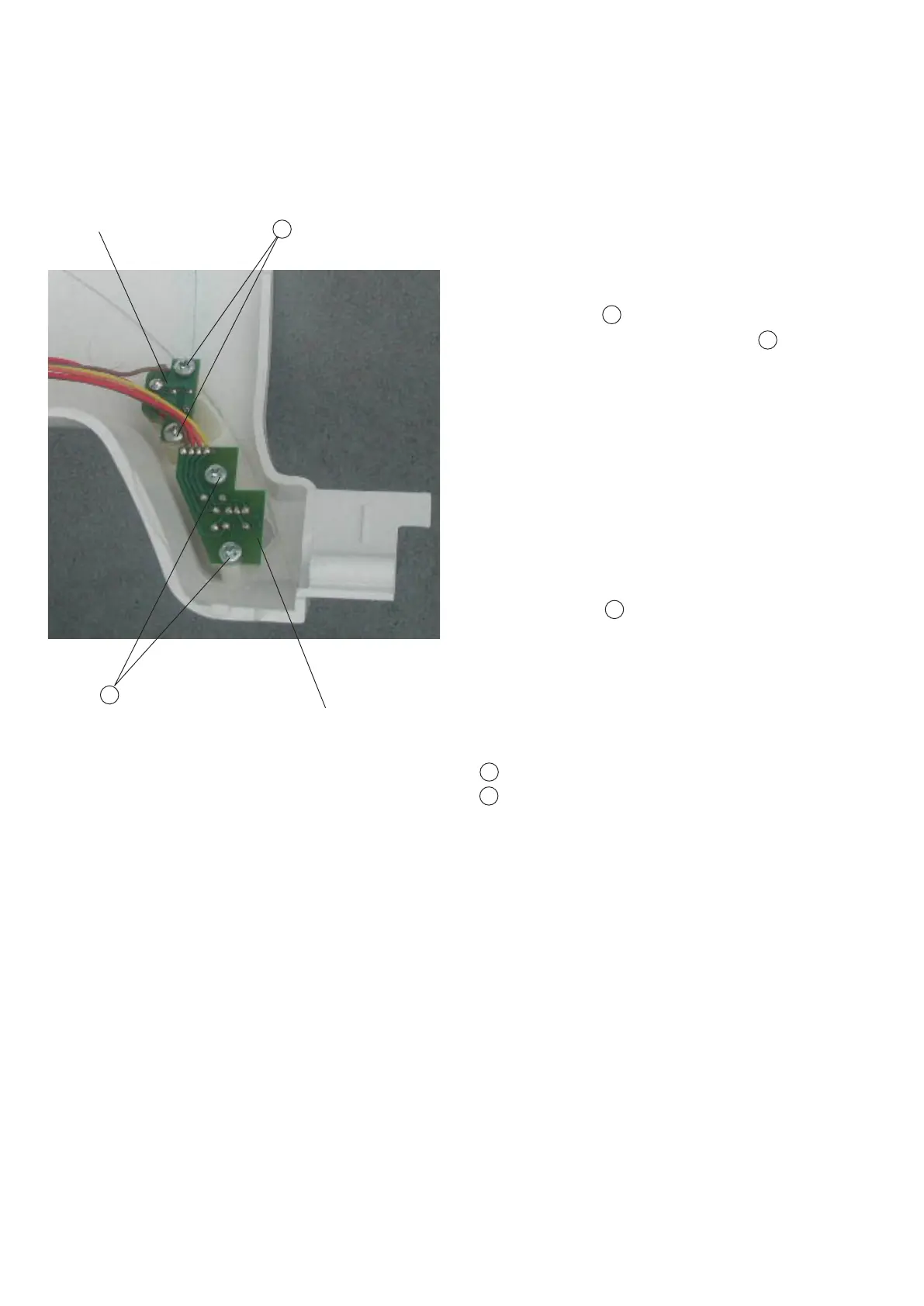
PrintedcircuitboardF2
Replacing Printed Circuit Board “F” & “F2”
To remove:
1. Remove the front cover. (See page 6)
2. Pull out the connector from the printed circuit
board “A” (Mainboard).
3. Remove Screws (2 pieces) and remove
the Printed circuit board “F” (Start/Stop) .
To attach:
4. Follow the above procedure in reverse.
A
B
To remove:
1. Remove the front cover. (See page 6)
2. Pull out the connector from the printed circuit
board “A” (Mainboard).
3. Remove Screws (2 pieces) and remove
the Printed circuit board “F2” (Start/Stop) .
To attach:
4. Follow the above procedure in reverse.
Screws
Screws
B
A
PrintedcircuitboardF
B
A
B