30
OPERATION MIG
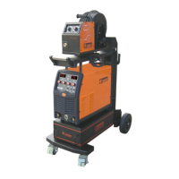
MIG/MAG welding
Insert the welding torch (C) into the “Euro connector for torch in MIG”
output socket on the front panel of the machine and ghten it.
Insert the trailing cable plug (A) into the “+” output terminal
of the welding machine and ghten it clockwise.
Insert the work return lead cable plug (B) into the
“-” output terminal on the front panel of the
welding machine and ghten it clockwise.
Install the welding wire on the spindle adapter.
Connect the cylinder equipped with a gas
regulator to the gas inlet on the back
panel of the machine with a gas hose.
Correctly set the gas ow.
Ensure that the roller groove size on the
ed drive roll matches the contact p size of the welding torch and the wire size being used.
Release the pressure arm of the wire feeder to thread the wire through the guide tube and into the
drive roll groove and then adjust the pressure arm, ensuring no sliding of the wire. (too much pressure
will lead to wire distoron which will aect wire feeding performance).
Pressing the wire inch buon will acvate the feed motor only and will start to feed the wire through
the torch unl the wire comes through the contact p. You are now ready to start MIG welding.
MIG welding using gasless, self shielded MIG wire
Insert the welding torch (D) into the “Euro connector for torch in MIG”
output socket on the front panel of the machine and ghten it.
Insert the work return cable plug (E) into the “+” output terminal
of the welding machine and ghten it clockwise.
Insert the trailing cable plug (F) into the “-” output
terminal on the front panel of the welding machine
and ghten it clockwise.
Install the wire spool on the spindle
adapter ensuring that the roller groove
size on the drive roll ed matches
the contact p size of the
welding torch and the
wire size being used.
Release the pressure arm of the wire feeder to thread the wire through the guide tube and into the
drive roll groove.
Adjust the pressure arm ensuring no sliding of the wire. (Too much pressure will lead to wire distoron
which will aect wire feeding performance).
Pressing the wire inch buon will acvate the feed motor only and will start to feed the wire through
the torch unl the wire comes through the contact p.
You are now ready to start MIG welding.
A
B
E
F
C
D
 Loading...