Instructions for CBT 1000+1000E System:
The BRACKET ASSEMBLY consists of 2 pieces of SPEAKER BRACKETS (the parts that mount on the
speaker), 2 pieces of WALL BRACKETS (the parts that mount on the wall), 2 pcs of SWIVEL BRACKETS
(which get added to the SPEAKER BRACKETS if utilized for horizontal swivel/pan aiming capability), and an
ARM LINK (which is utilized for the larger tilt angles).
1) RUN WIRING -- Run the wiring from the power amplier to the location desired for mounting the JBL
CBT Loudspeakers. Note: Connect wire to speaker terminals at a point in the installation process when
convenient for your installation circumstances.
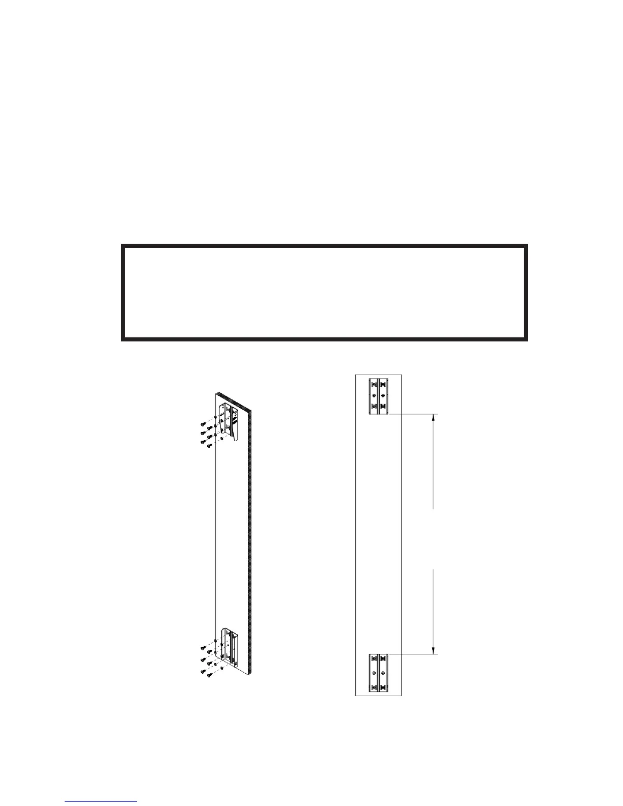
2) ATTACHING WALL BRACKET TO WALL -- Using a level to ensure that the WALL BRACKET is straight,
secure the WALL BRACKET to the wall. Be sure to use the appropriate wall anchors for attaching the
bracket. Use as many of the screw holes as possible for maximum integrity and safety.
CAUTION: Installation must be done by qualied persons
using safe rigging standards.
The installer is responsible for proper selection and use of mounting hardware
to properly and safely wall-mount the speakers.
Hardware attaching WALL BRACKET to wall is not
included. Utilize proper hardware for particular wall
structure.
Spacing needed between upper and lower
WALL BRACKET parts with CBT1000 and
CBT1000E depends on whether speaker will be set
with down-tilt or up-tilt
Spacing:
1200 mm (47-1/4”) for Down-Tilt
1216 mm (47-7/8”) for Up-Tilt
9
(Drawings show upper
and lower bracket
orientation as set for
down-tilt or 0°. Wall
brackets to be reversed
in location and ipped for
up-tilt applications (see
further instructions).