14
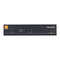
3.2 Front Panel Controls and Indicators
A. Level: Detented rotary level control, one per channel.
B. Meter Group (one per channel):
• Clip Indicator: Red LED turns at the threshold of audible distortion.
• Signal Indicator: Green LED flashes when a very low-level signal (Threshold
-40dB) is present at input. May be used for troubleshooting cable runs.
C. Power Indicator: On/off switch applies AC power to the amplifier.
3.3 Rear Panel Controls and Connectors
D. AC Line Connector
E. Output Connectors: 4-pin Euroblock connectors for dual loudspeakers.
F. Amplifier Parameter Switchers: Slide DOWN to turn on these functions. Slide UP to turn
them off. The parameter switchers are numbered as below:
1. CH1 70Hz highpass filter
2. CH2 70Hz highpass filter
3. CH1 peak limiter
4. CH2 peak limiter
5. Auto standby
G. RCA Connectors
H. Euroblock Connectors: Two 3-pin Euroblock connectors each accept a balanced or
unbalanced line-level input signal.
A
C
B
输入
70Hz 高通滤波
限幅
自动待机(STBY)
输入
70Hz 高通滤波
限幅
输出
输出
输入功率 50W
100-240V~50/60Hz
D E F G
H
Figure 3.3 Rear View
Figure 3.2 Front View