The LinX shaft produces a strong magnetic field and the effect of this field on surrounding parts and components
should be considered during system design. Relevant effects of the strong magnetic field include:
1. Attraction between the shaft and ferrous or magnetic objects. This magnetic force may cause bending in
longer shafts.
2. Ferrous objects and material can become magnetised if located close to the shaft or moved through a
region close to the shaft. To avoid unwanted magnetisation of susceptible components the system
should be designed with an air gap (non-magnetic region) of at least 150mm between the surface of the
shaft and the component that may be magnetised.
3. In a machine tools application swarf may become trapped on the shaft due to magnetic attraction. This
may occur even if the shaft is protected by a bellow. It is recommended that an air gap (non-magnetic
region) of 150mm or greater be kept between steel swarf and the surface of the shaft.
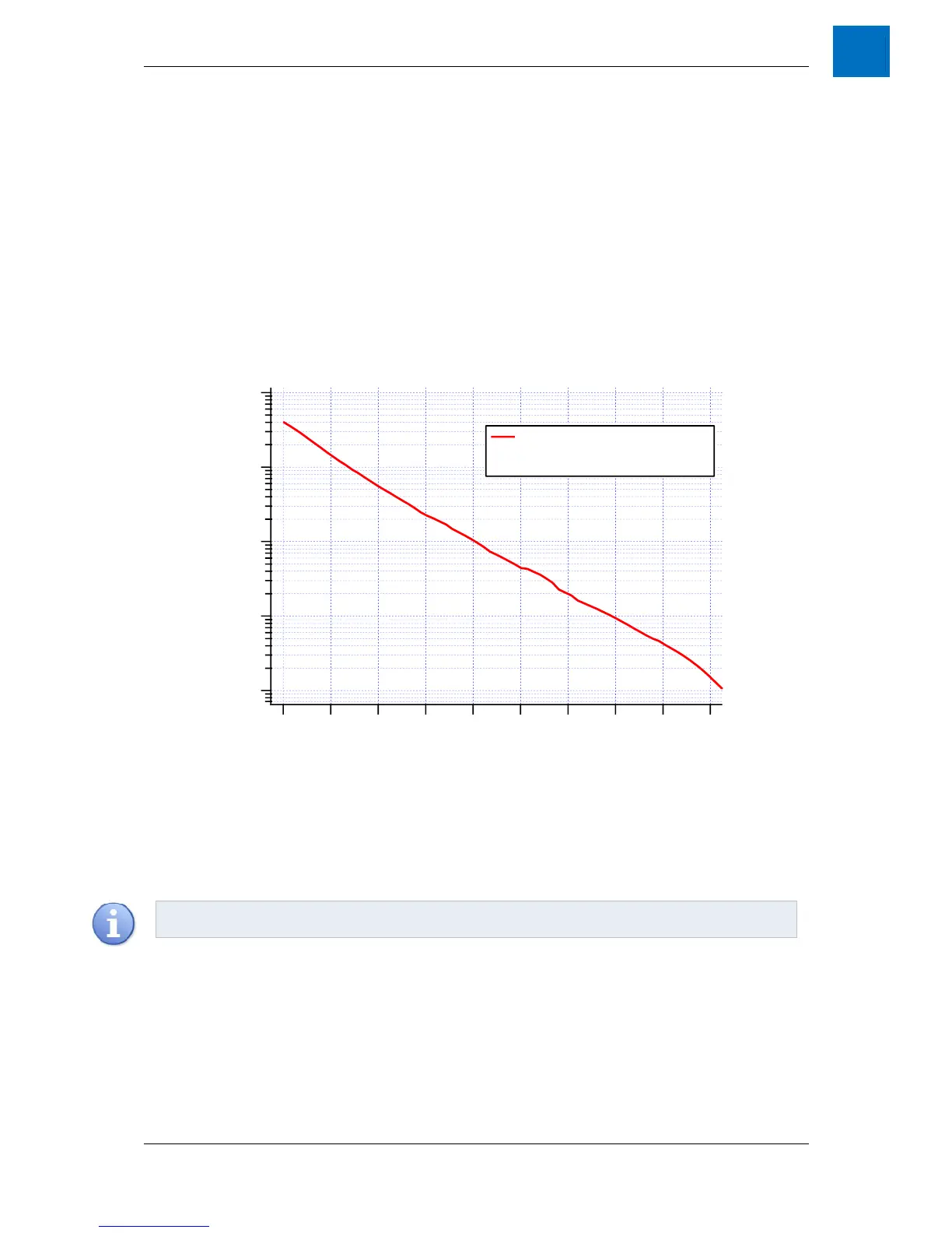
4. When using a magnetic position sensor ensure that it is located far enough from the shaft that the
magnetic field is within the working limits of the sensor. The shaft field strength as a function of distance
from the shaft is shown in Figure 4-1.
The effects of the shaft magnetic field on surrounding components can be minimized by using non-magnetic
materials wherever possible.
Figure 4-1 – Shaft magnetic field strength with distance
The shaft must be mounted to ensure that concentricity with the central bore of the forcer. The nominal radial air
gap between the forcer and shaft of 1mm should ideally be maintained for the entire stroke. The air gap is non-
critical for operation as long as the forcer and shaft do not come into contact. Contact will result in an increase in
friction and wear on the cylindrical linear motor.
bjected to temperatures above 13C. Therefore, consideration
tinuous operating current of the application for the
expected ambient temperature.
Forcer 4.2.3
Forcer model selection is dependent upon the peak force, continuous force and peak velocity of the application.
Each needs to be identified before a forcer can be accurately specified.
10
-4
10
-3
10
-2
10
-1
10
0
B field (T)
180160140120100806040200
Distance from surface of shaft (mm)
Shaft Magnetic Field Strength
NB: The strength of the Earth's
magnetic field is on the order of 50µT.