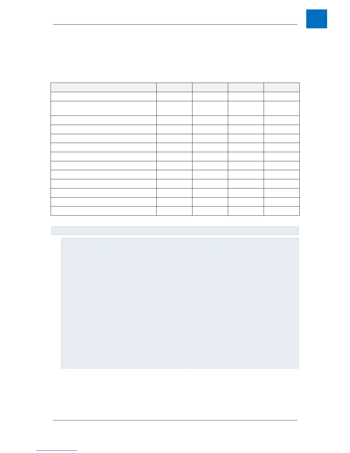
Table 5-1 - Electrical Specifications
NOTES:
1. The maximum continuous force and current when the forcer is stationary (worst-case) is given for both
fluid cooling (first figure) and air-natural cooling (second figure). Air-cooled ratings are based on an
ambient temperature of 25°C and fluid cooled ratings based on a coolant temperature 25°C (flow rates
in Table 5-2). The quoted air-cooled ratings assume a standard mounting configuration (see Figure 3-2)
where the motor is attached to a steel carriage via two metal brackets.
2. The maximum continuous ratings for both Fluid and Air cooling are based on a winding temperature of
130°C absolute ma
3. The maximum peak force and current is a limitation due to permanent magnet characteristics and
should never be exceeded even for a short time.
4. If the linear motor is used repetitively at peak forces in excess of the nominal, the equivalent rms loading
shall be taken into account, along with forces that are below the nominal figure. The application duty
cycle should be calculated over a period of 10 minutes. Further, sufficient Voltage must be available
from the Servo Drive to overcome both the resistance, and the back-emf of the linear motor (depending
on the speed). Refer to 5.2 Force vs. Speed Characteristics.
5. and are twice the per-
phase parameters. The resistance is taken at 25°C. Resistance values will increase by 40% at the
design operating temperature of 130°C. Inductance measurement is performed at 1kHz.
6. The linear motor winding insulation is designed for PWM operation at a maximum motor voltage of 420V
rms line-line from a maximum DC Bus Voltage of 680V DC.