LinX Series Linear Motor - User Guide
32 D-000168 Rev 02 ANCA Motion
3. Electrical wiring between the encoder and servo drive (On an incremental encoder, inversion of
one of the quadrature signals is sufficient).
4. Swap any two phases of UVW.
The recommended method for matching the movement direction of the motor and encoder is updating the
software configuration in the drive (1) as this involves no physical change to the system.
Electrical 6.3
DANGER HIGH VOLTAGE: Ensure power has been completely disconnected before touching electrical
connections. Electrical shock can cause serious or fatal injury.
Motor Power and Temperature Feedback 6.3.1
DANGER: The shaft must be earthed to prevent the possiblility of electric shock during motor operation.
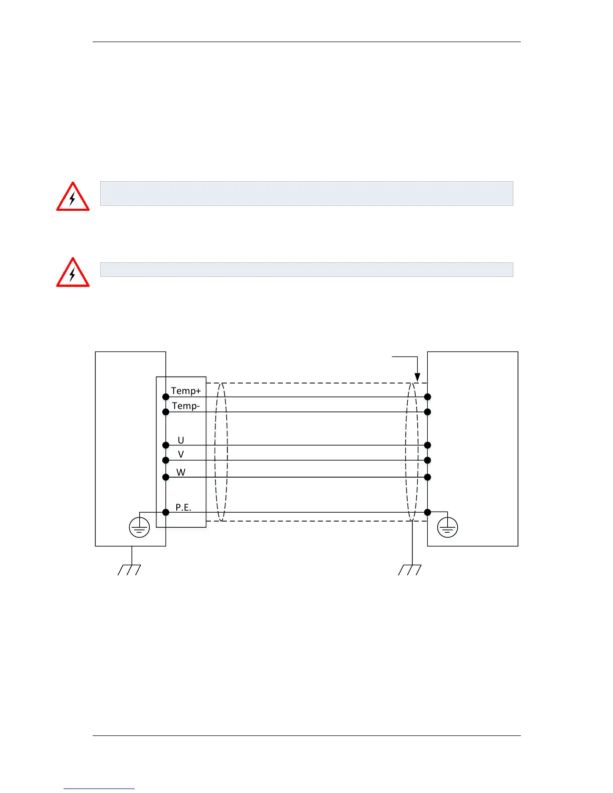
The power supply and temperature signal feedback are both supplied via the LinX forcer connector. Connector
pin allocations and recommended wire gauge can be found in section 5.3.3 Connector. Please refer to the servo
drive documentation for further information on how to wire in the motor power supply and temperature sensor.
Motor Servo Drive
Temp+
Temp-
U
V
W
P.E.
Earth shield
Connected 360°
to gear tray
Minimise
unshielded
lengths
Temp+
Temp-
U
V
W
Figure 6-13 - Connection between motor and servo drive
If using Tandem Forcers and the orientation of the 2
nd
forcer is reversed, then the V and W wires also need to be
reversed to ensure both forcers move in the same direction. Refer to Section 6.2.2.2 for more information.
Sensors 6.3.2
Connect the sensors such as home switches and dead stops that are to be used to the servo drive as specified in
the sensor and servo drive documentation.