9 - 1
Section F Transmission
9803/6410
Section F
9 - 1
Issue 1
Reduction Gear - JS130
Dismantling
Refer to the following pages:
7 - 1 and 7 - 3 (illustrations)
7 - 4 to 7 - 5 (component list)
In the following procedures, the part numbers in bold type
(e.g. 170) correspond with the numbers on the illustrations.
Before attempting to dismantle the reduction gear, drain all
oil, blank all inlet and outlet ports and wash the outer
surfaces with a suitable solvent to remove all dirt and dust.
Dry using compressed air.
1 Place the traction motor/reduction gear assembly on
the bench with cover 8 uppermost.
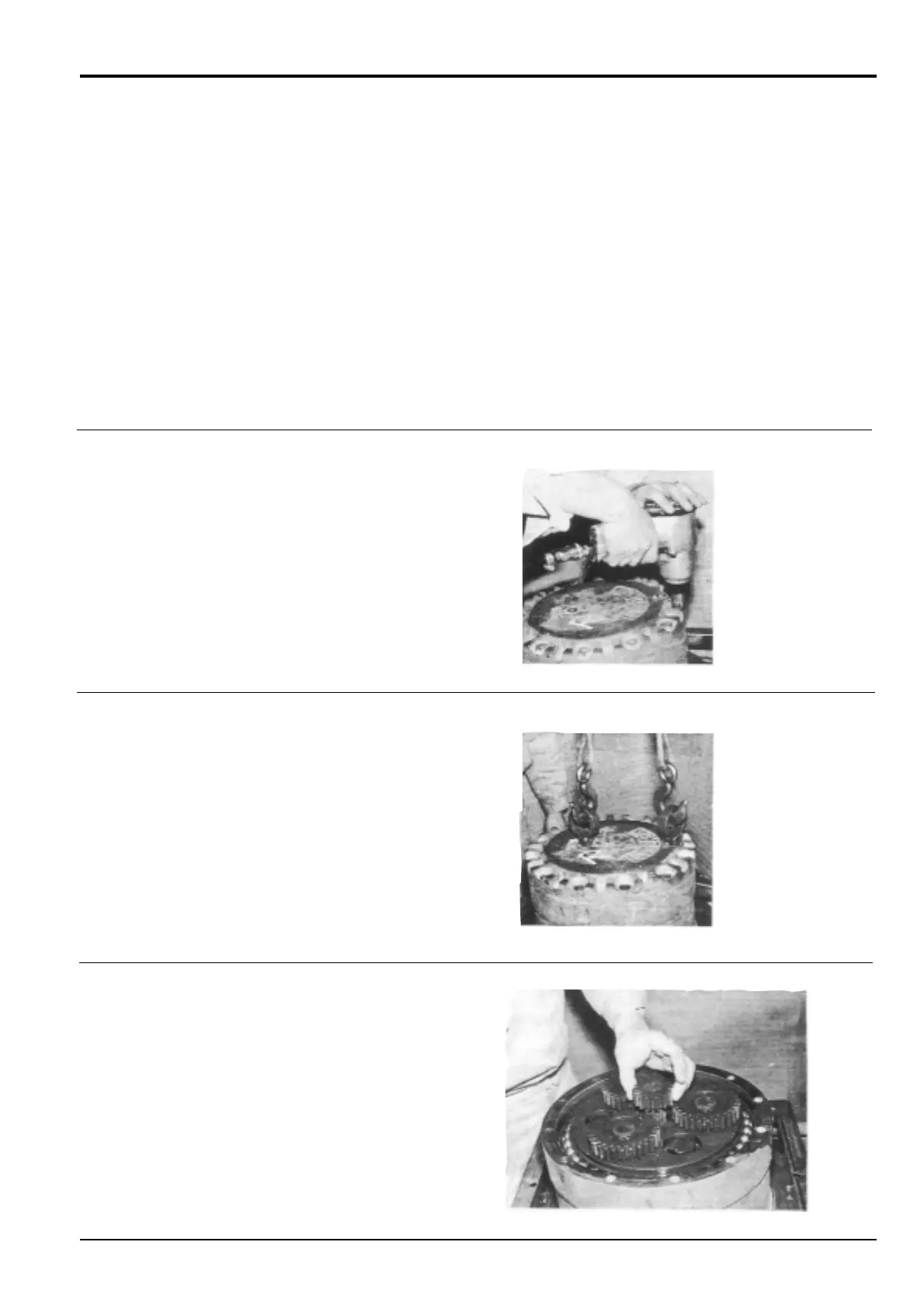
Remove the two plugs 33. Remove the twelve bolts 35
and super lock washers 36.
2 Install eye bolts into the tapped holes vacated by plugs
33.
Attach suitable lifting gear to the eye bolts and remove
cover 8, if necessary gently tapping the rim with a
plastic hammer to overcome the resistance of ‘O’-ring
29.
Remove and discard ‘O’-ring 29 from cover 8.
Drain the lubricant (3.6 litres (0.79 gal)) from the
reduction gear.
3 Remove snap ring 24 and input gear 6 from shaft 102.
Make different alignment marks across each sub assembly
joint face as an aid to assembly.
During dismantling, record the number and dimensions of
shims. Take care to reassemble in the same manner.