3 - 19
Section E Hydraulics
9803/6020
Section E
3 - 19
Issue 1
Schematics
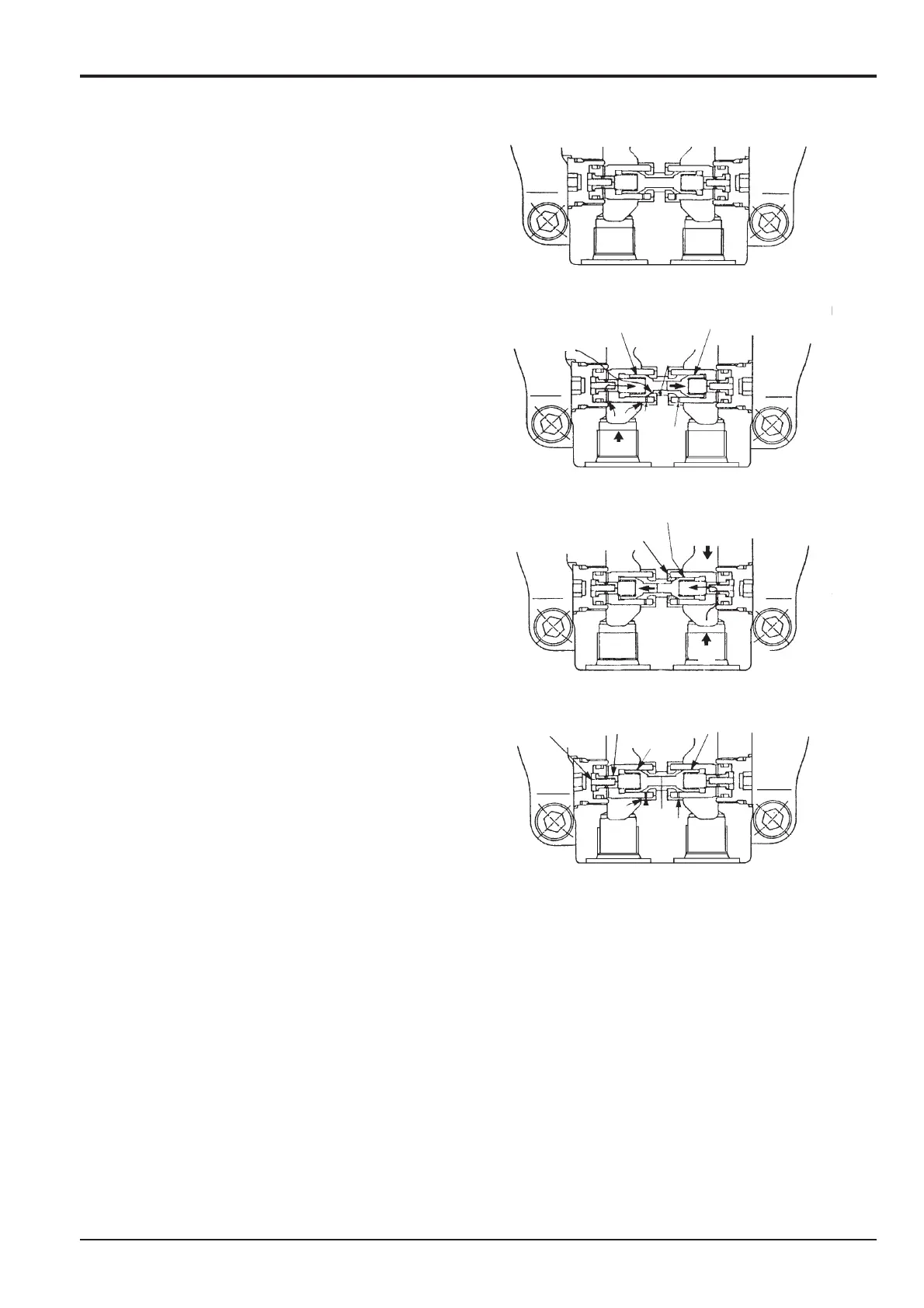
Swing Over-run Prevention Operation
The swing over-run prevention valve is installed inside
the swing motor to prevent the swing back when the
swing is stopped.
1 No swing (Figure 1)
The swing over-run prevention valve is in neutral state.
2 Swing acceleration, during swing (Figure 2)
When operating the swing, port H and port J are
connected through the small hole E the intermediate
chamber D and the small hole F. The oil flows out of port
J immediately. The high pressure oil enters into the back
chamber of the poppet B. This causes the poppet to
move towards the right side as in figure 2
3 Swing Braking (Figure 3)
When operating the swing brake from figure 2 status,
the motor is activated by the pump, with both ports H
and J locked.
The pressure changes from high pressure to low
pressure on port H and from low pressure to high
pressure on port J. Since port J is connected with the
intermediate chamber poppet B is pushed open.
Port J, the intermediate chamber D and port H are
connected through the small hole F and the small hole E,
a small amount of oil flows out from port J to port H,
eventually the poppet C will seal on seat K and the oil
flow will be cut.
4 Swing over-run (Figure 4)
After stopping swing, the motor returns to the opposite
direction by the remaining pressure from Port J. There is
probably high pressure in port H. Since port H is
connected with the intermediate chamber D, and port J
(connected through the small hole F and the small hole
E), a little oil flows out from port J to port H.
Because there is no close of pressure between port H
and port J, the back shaking is reduced.
The oil from the spring chamber on the back section of
the poppet B, and poppet C flows out through poppet N
and spring M via the control valve.
298480
Figure 1
Figure 2
Figure 3
Figure 4
A
B
D
C
G
E
B
J
H
C
L
K
L
J
H
M
N
C
B
D
P
E
HJ
F