E-7 E-8
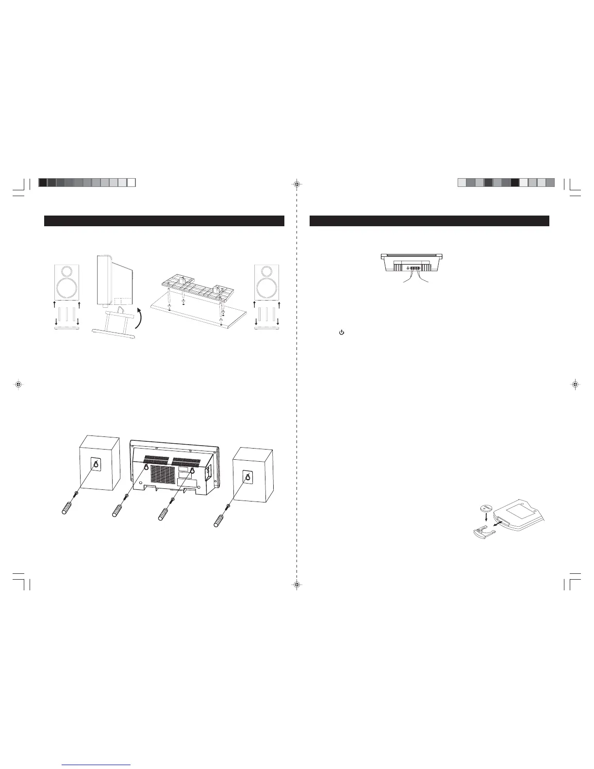
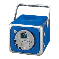
FOR TABLE TOP USE
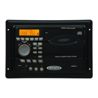
FOR WALL MOUNTING
1. Use the wall-mountingtemplate supplied withtheunitto make marks onthe wall for the anchors. Make s ure
themarksarelevel.
2. Drill 1/4" holes on the marks. P leas e refer to the appendix s heet attached with this ins truction manual
for details .
3. Ins ert the plas tic anchor s upplied with unit until it is flus h with the wall.
4. I ns e rt the s c rew a nd tighte n the s c re w 4mm a wa y from the wa ll. ( Approxima tely the width of 2 pennie s )
H ang the ma in unit a nd s pea ke rs to the s cre w a s indic ate d below:
GETTING STARTED
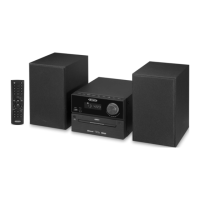
SPE AK E R CONNE CTION
1. Insertthe speaker cables by pushing downthe terminal lever ofthe LeftSpeakerTerminal andthe R ight
Speaker Terminal (25).
2. C onnect the s peaker to S pea ker Terminals (25), with red wire to red terminals and black wire to black
termina ls .
LINE IN (AUX IN) CONNE CTION (OPTIONAL)
1. C onnect the left and right channel R C A plug (not included) into the AUX IN J ack (21) and the other end
to your external player. Make sure the polarity of the right and the left channel is correct, Red to Right, White to Left.
2. Press the
Following the diagrams below, insert the stands into the base and attach the main unit and
speakers as shown.
NOTE: A screwdriver is needed for attacking the stands to the main unit and stands.
ON/STANDBY Button (10/H1) toswitch on the unit.
3. PressFunction Button (3/H3). “AUX”Indicator (#D5) appears inthe display (18).
4. Play the auxiliary input source.
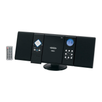
SUBWOOFERCONNECTION (OPTIONAL)
1. Connect one endof a RCA plug (not included) into the SubwooferJack (24) and the other end to the
subwoofer (not included).
2. Turn on the unit andthen your subwoofer.
ANTENNACONNECTION
FM: Unwrap and fully extend theFMAntenna wire(22) for best reception.If stereo broadcasting isreceived,
Stereo Indicator (#D15) will light.
AM: The unit isbuilt-in with a directionalferrite antenna, reposition the unit for best reception.
POWER SUPPLY
This Front LoadingDual CD System operatesfromAC120V~60Hz linepower supply.
The remote controlunit operates onone 3V “CR2025”lithium battery.Topower upthe remotecontrol, removethe
plastic insulationtab sticking out ofthe battery compartment.
AC POWER CONNECTION
Connect the power cord to anAC120V~60Hz power source.
REPLACING BATTERY IN THEREMOTE CONTROL
1.Turn over theremote control, and removethe battery door.
2. Install 1“CR2025” lithium battery accordingto the polarity diagram
on the battery compartment.
3. Replace the batterydoor.
INSTALLATION
JMC-670 INSTRUCTION MANUAL JMC-670 INSTRUCTION MANUAL
HX-1056M3 IB JENS 001 REV0.P65 7/20/2005, 2:51 PM5