Wiring
WARNING! Only connect the unit to a 12-volt
power
supply with propergrounding.
Complete wiring as illustrated in the wiring diagram on page
4.
Once the wiring is complete, reconnect the bat-
tery negative terminal. If there is no ACC available, connect the ACC lead to the power supply with a switch.
NOTE: When replacing
a fuse, be sure to use correct type
and
amperage to avoid damaging the radio. The
VM9314 uses one
15 amp fuse, located in the black filter box in-line with the main wire hamess.
Final
Installation
After completing the wiring connections, turn the unit on to confirm operation (ignition switch must be on). If
unit does not operate, recheck all wiring until problem is corrected. Once proper operation is achieved, turn off
the ignition switch and proceed with final mounting
of
the chassis.
ISO-DIN
Installation
II
Slide radio chassis into dash opening and secure.
II
Re-install dash panel.
D
fJ
II
II
D
fJ
II
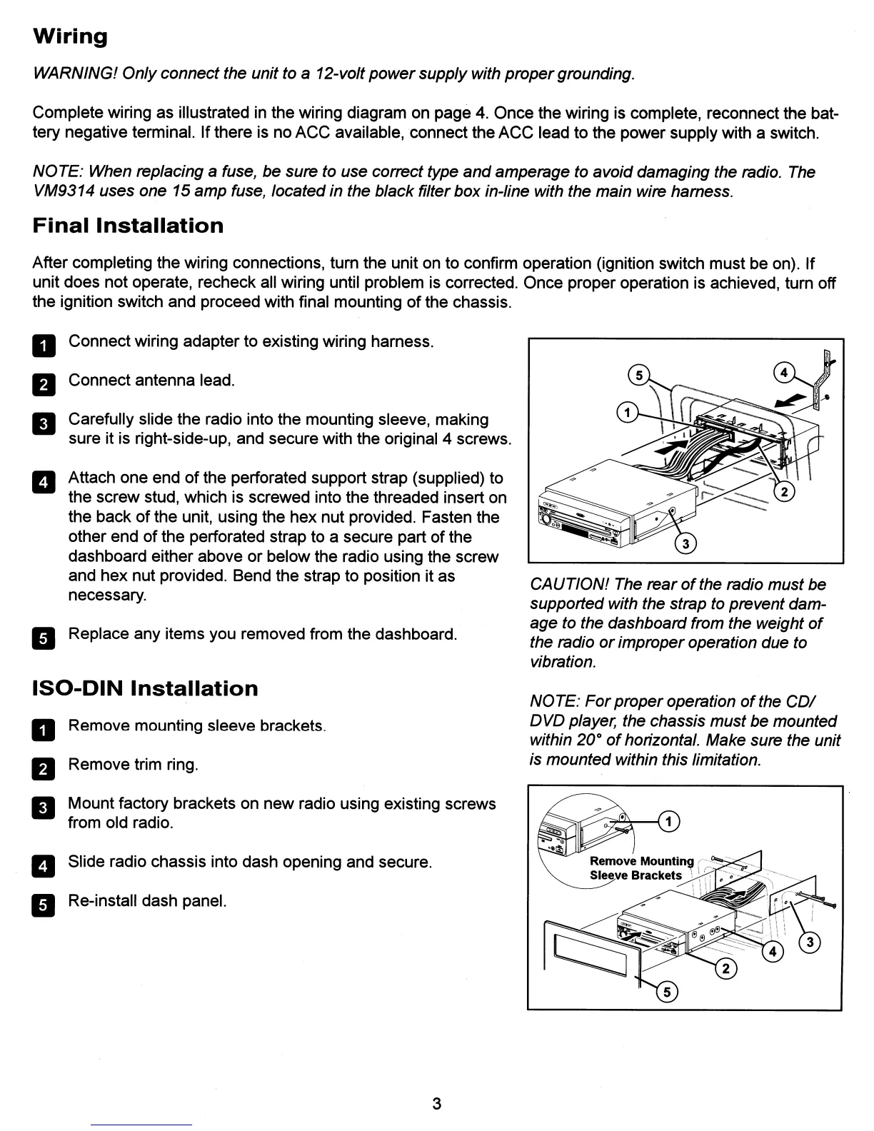
Connect wiring adapter to existing wiring harness.
Connect antenna lead.
Carefully slide the radio into the mounting sleeve, making
sure it is right-side-up, and secure with the original 4 screws.
Attach one end
of
the perforated support strap (supplied) to
the screw stud, which is screwed into the threaded insert on
the back
of
the unit, using the hex nut provided. Fasten the
other end
of
the perforated strap to a secure part
of
the
dashboard either above or below the radio using the screw
and hex nut provided. Bend the strap to position it as
necessary.
Replace any items you removed from the dashboard.
Remove mounting sleeve brackets.
Remove trim ring.
Mount factory brackets on new radio using existing screws
from old radio.
3
CAUTION! The
rear
of
the radio must be
supported with the strap to prevent dam-
age to the dashboard from the weight
of
the radio
or
improper operation due to
vibration.
NO
TE:
For
proper operation
of
the
COl
DVD player, the chassis must be mounted
within
20°
of
horizontal. Make sure the unit
is mounted within this limitation.