15
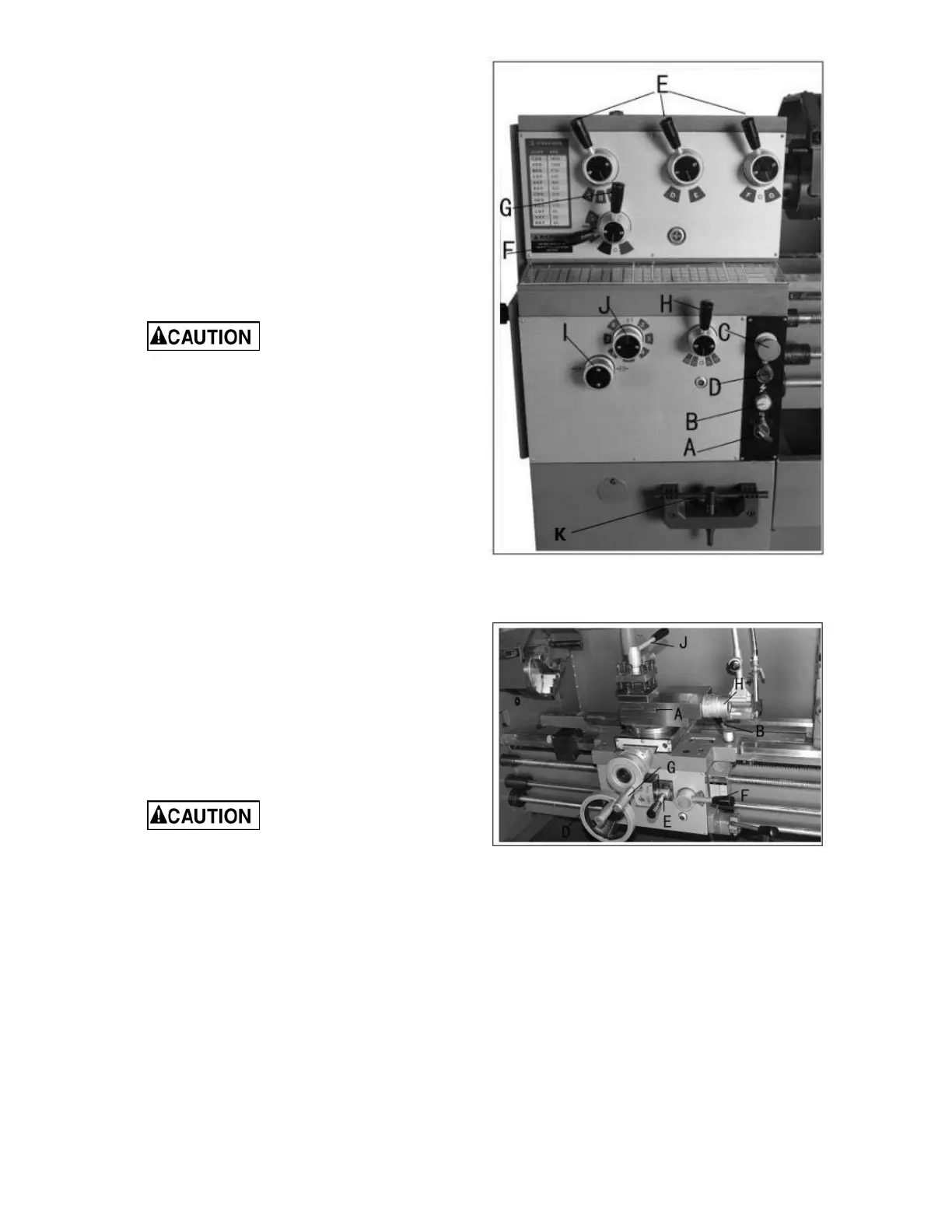
2. Headstock Gear Change Levers (E, Fig. 14)
– located on front of headstock. Move levers
according to speed chart for desired setting.
3. Leadscrew/Feed Rod Directional Lever (F,
Fig. 14) – located on front of headstock.
Moving the lever up causes carriage travel
toward the tailstock; moving the lever down
causes carriage travel toward the headstock
(when chuck is spinning in forward or
counterclockwise direction). Do not move
lever while machine is running.
4. Feed/Lead Selector Lever (G, Fig. 14) –
located on the front of the headstock. Used
whenever setting up for threading or feeding.
In the "A" position, never
run the lathe higher than 650 RPM.
5. Feed/Lead Selector Lever (H, Fig. 14) –
located on the front of the gearbox. Used in
setting up for feeding and threading.
Positions "F" and "D" are for the feed rod.
Positions "E" and "C" are for the feed screw.
Position "0" is neutral.
6. Lock Knob (I, Fig. 14) – located on the front
of the gearbox. With the knob in the six
o'clock position, feed/lead selector knob (J,
Fig. 14) may be adjusted. With the knob in
the twelve o'clock position, the feed/lead
selector knob (J, Fig. 14) is locked.
7. Feed/Lead Selector Knob (J, Fig. 14) –
located on front of the gearbox. Used for
setting up for feeding and threading.
8. Compound Lock (A, Fig. 15) – hex socket
screw located on left side of compound. Turn
clockwise to lock and counterclockwise to
unlock.
9. Carriage Lock (B, Fig. 15) – lock handle
located on top of carriage. Turn clockwise to
lock. Turn counterclockwise to unlock.
Carriage lock must be
unlocked before engaging automatic
feeds or damage to lathe may occur.
10. Longitudinal Traverse Hand Wheel - (D,
Fig. 15) – located on the apron assembly.
Rotate hand wheel clockwise to move the
apron assembly toward the tailstock. Rotate
the wheel counterclockwise to move the
apron assembly toward the headstock.
11. Feed Selector (E, Fig. 15) – located in the
center front of the apron assembly. Pushing
lever to the left and down activates the
crossfeed function. Pulling lever to the right
and up activates the longitudinal function.
Figure 14 (repeated)
Figure 15