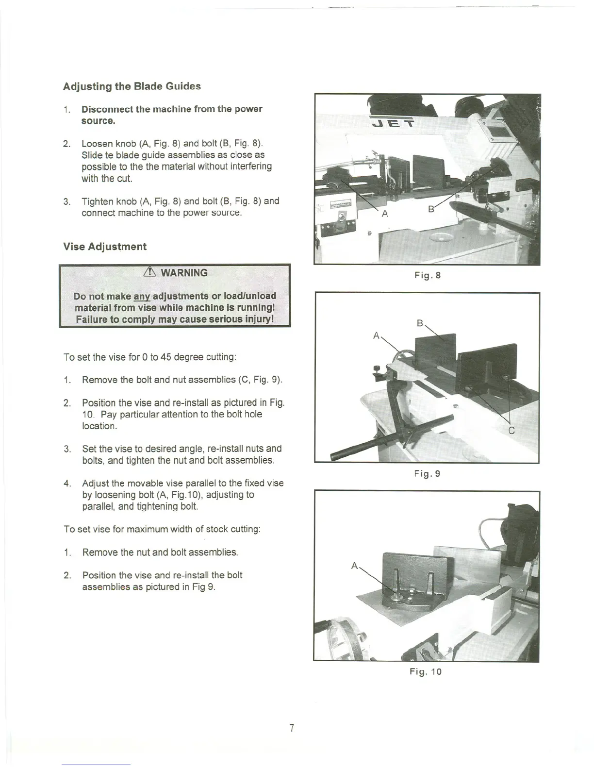
Adjusting the Blade Guides
1. Disconnect the machine from the power
source.
2. Loosen knob (A, Fig. 8) and bolt (B, Fig. 8).
Slide te blade guide assemblies as close as
possible to the the materialwithout interfering
with the cut.
3. Tighten knob (A, Fig. 8) and bolt (B, Fig. 8) and
connect machine to the power source.
Vise Adj ustment
.!..) WARNING
To set the vise for 0 to 45 degree cutting:
1.
Remove the bolt and nut assemblies(C, Fig. 9).
2.
Position the vise and re-install as pictured in Fig.
10. Pay particular attention to the bolt hole
location.
3. Set the vise to desired angle, re-install nutsand
bolts, and tighten the nut and bolt assemblies.
4. Adjust the movable vise parallelto the fixedvise
by loosening bolt (A, Fig.10),adjusting to
parallel, and tightening bolt.
To set vise for maximum width of stock cutting:
1. Remove the nut and bolt assemblies.
2. Position the vise and re-installthe bolt
assemblies as pictured in Fig 9.
Fig.8
"-
Fig.9
Fig.10
7

 Loading...