11
Read and understand the entire
contents of this manual before attempting
assembly or operation. Failure to comply may
cause serious injury.
5.0 Setup and assembly
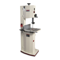
5.1 Shipping contents
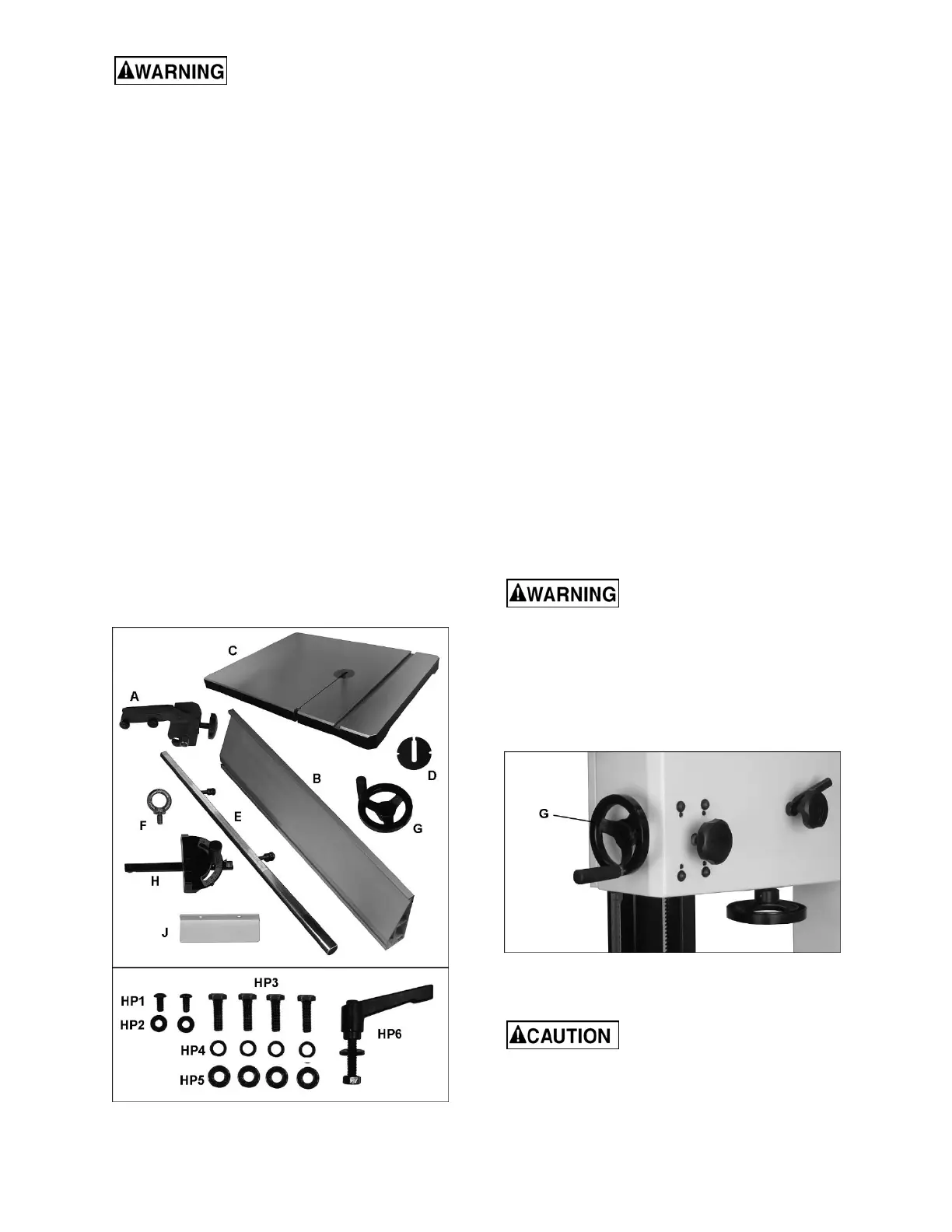
Refer to Figure 5-1.
1 Band saw (not shown)
1 Fence body – A
1 Resaw fence – B
1 Table – C
1 Table insert – D
1 Guide rail – E
1 Lifting ring – F
1 Handwheel with handle – G
1 Miter gauge assembly – H
1 Bracket (model JWBS-20 only) – J
1 Owner’s manual (not shown)
1 Warranty card (not shown)
1 Hardware package containing:
2 Socket hd button screws – HP1
2 Flat washers – HP2
4 Hex cap screws – HP3
4 Lock washers – HP4
4 Flat washers – HP5
1 Table slot handle assembly – HP6
Figure 5-1: contents
5.2 Tools required for assembly
The tools listed below are not included but are
required for assembly.
1 2.5mm hex key
1 3mm hex key
1 straight edge
1 17mm wrench
1 13mm wrench
5.3 Unpacking and cleanup
Remove crate and packing material from band saw
except for the transport skid on the bottom. Inspect
the machine for damage. Report any damage to
your distributor and shipping agent. Do not discard
packing material until machine is assembled and
running satisfactorily.
Move the saw to its permanent working location.
The site should be dry, well lit, and have enough
room to handle long stock and servicing or
adjustment of the machine from any side.
Install lifting ring atop band saw, and use hoist to
move saw off skid. Clean all rust protected surfaces
with a mild solvent or diesel fuel and a soft cloth. Do
not use lacquer thinner, paint thinner, or gasoline,
as these will damage painted surfaces.
5.4 Assembly
Band saw must be
disconnected from power source during
assembly procedures. Failure to comply may
cause serious injury.
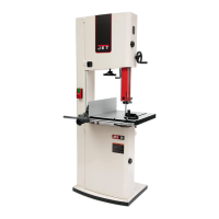
5.5 Handwheel
Install handwheel (G, Figure 5-2) onto shaft, and
tighten two set screws with 3mm hex key.
Figure 5-2
5.6 Installing and aligning table
Table is heavy. Mounting with
the help of another person is recommended.
Refer to Figures 5-3 through 5-4:
1. Slide table so that saw blade passes through
slot (A).