11
If repair or replacement of the electric cord or plug
is necessary, do not connect the equipment-
grounding conductor to a live terminal.
Check with a qualified
electrician or service personnel if the grounding
instructions are not completely understood, or if
in doubt as to whether the tool is properly
grounded. Failure to comply may cause serious
or fatal injury.
Use only 3-wire extension cords that have 3-prong
grounding plugs and 3-pole receptacles that accept
the tool's plug.
Repair or replace damaged or worn cord
immediately.
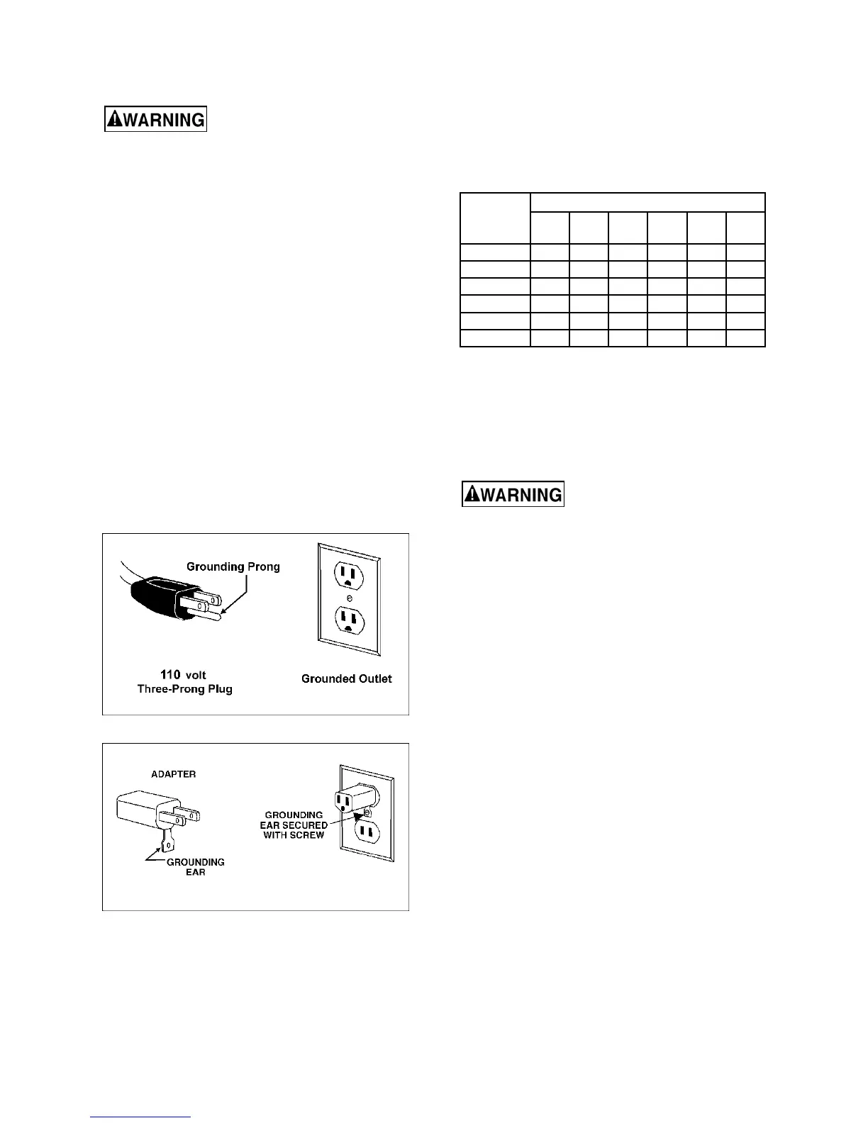
This tool is intended for use on a circuit that has an
outlet that looks like the one illustrated in Figure 7-
1. An adapter, shown in Figure 7-2, may be used to
connect this plug to a 2-pole receptacle as shown in
Figure 7-2 if a properly grounded outlet is not
available. The temporary adapter should be used
only until a properly grounded outlet can be installed
by a qualified electrician. The green-colored rigid
ear, lug, and the like, extending from the adapter
must be connected to a permanent ground such as
a properly grounded outlet box.
In Canada, the use of a temporary adaptor is not
permitted by the Canadian Electrical Code, C22.1.
Figure 7-1
Figure 7-2
7.2 Extension cords
The use of extension cords is discouraged; try to
position machines near the power source. If an
extension cord is necessary, make sure it is in good
condition. When using an extension cord, be sure to
use one heavy enough to carry the current your
product will draw. An undersized cord will cause a
drop in line voltage resulting in loss of power and
overheating. Table 1 shows correct size to use
depending on cord length and nameplate ampere
rating. If in doubt, use the next heavier gauge. The
smaller the gauge number, the heavier the cord.
Recommended Gauges (AWG) of Extension Cords
Amps
Extension Cord Length *
25
feet
50
feet
75
feet
100
feet
150
feet
200
feet
< 5 16 16 16 14 12 12
5 to 8 16 16 14 12 10 NR
8 to 12 14 14 12 10 NR NR
12 to 15 12 12 10 10 NR NR
15 to 20 10 10 10 NR NR NR
21 to 30 10 NR NR NR NR NR
*based on limiting the line voltage drop to 5V at 150% of the rated
amperes.
NR: Not Recommended.
Table 1
8.0 Adjustments
Disconnect sander from power
source before making adjustments.
8.1 Drum Height Control
Drum height and depth of cut are controlled by
height adjustment handle (see Figure 5-1). Rotating
handle clockwise lowers drum, counterclockwise
raises it. One revolution of handle will move drum
approximately 1/16” (or 1/4 turn = approx. 1/64”), as
shown on the label below handle.
8.2 Depth scale
The depth scale indicates distance between bottom
of sanding drum and top of conveyor belt.
Adjustment is performed by “zeroing” the scale.
1. Unplug sander from power source.
2. With an abrasive strip on drum, lower drum to
where it touches top of conveyor belt.
3. At this drum position, the depth scale pointer
should align with zero mark on scale. If it does
not, loosen two screws (Figure 8-1) and raise or
lower scale until zero aligns with the pointer.
4. Retighten screws.
Note: Depending on desired accuracy, you may
need to repeat this process when installing different
abrasive grits.
 Loading...