9
6.0 Setup and assembly
Open shipping container and check for shipping
damage. Report any damage immediately to your
distributor and shipping agent. Do not discard any
shipping material until the Lathe is assembled and
running properly.
Compare the contents of your container with the
following parts list to make sure all parts are intact.
Missing parts, if any, should be reported to your
distributor. Read the instruction manual thoroughly
for assembly, maintenance and safety instructions.
6.1 Shipping contents
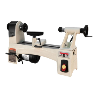
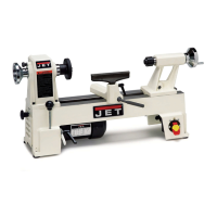
Carton contents (see Figure 6-1)
NOTE: Some parts shown below may be pre-
installed on the lathe.
1 Lathe
1 Live center – A
1 Spur center – B
1 Knockout rod – C
2 Tool caddies – D
4 Button head screws, 5/16 x 1/2 – E
2 Tool Rests, 10” and 6” – F
1 Face Plate, 3” – G
1 Operating Instructions & Parts Manual
1 Product registration card
Figure 6-1
6.2 Tools required for assembly
3/16” hex key (“Allen wrench”)
6.3 Cleaning
Exposed metal areas of the lathe, such as bed,
spindle and quill, have been factory coated with a
protectant. This should be removed with a soft
cloth and a cleaner-degreaser. Clean the bed
areas under the headstock, tailstock and tool
support base. Do not use an abrasive pad, and do
not allow solvents to contact painted or plastic
areas.
6.4 Mounting lathe to stand/table
For effective and safe operation, the lathe must be
mounted to the optional stand (see sect. 13.0) or a
workbench, using the four threaded holes in its
base (5/16”-18 UNC threads). See sect. 6.1 for
size and spacing of holes to be drilled in the
workbench.
6.5 Installing tool caddies
Refer to Figure 6-2.
1. Mount a tool caddy to each end of lathe with
two 5/16 x 1/2 button head screws.
Figure 6-2
6.6 Installing/removing face plate
Refer to Figure 6-3.
1. Push in spindle lock (A) and rotate spindle
using handwheel, until spindle lock engages.
Continue holding spindle lock in place.
2. Mount face plate by screwing it clockwise as
far as it will go onto spindle threads.
3. Release spindle lock.
4. To remove faceplate, engage spindle lock (A)
and turn faceplate counterclockwise.
 Loading...