EN
7
Rx 1
Rx 2
Ext.
Out/In
BATT
8
8 channel servo interface
100100100
input
voltage
4-14V
Input Voltage
SERVO
Rsat2 (Rx1)
Rsat2 (Rx2)
Jetibox/Sensor
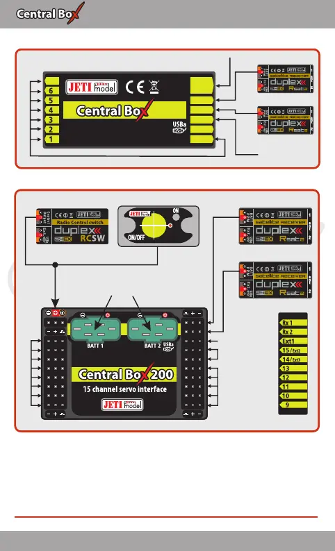
Fig. 12: Block diagram of Central Box 200 connection - EX Bus variant
RC Switch Magnetic Switch
Input Voltage
SERVO
Rsat2 (Rx1)
SERVO
Rsat2 (Rx2)
SERVO/Sensor
Jetibox/Sensor
input voltage
4-14V
Fig. 11: Block diagram of Central Box 100 connection - EX Bus variant
The Central Box can be configured in two ways:
• by JETIBOX connection (directly to the Central Box or wirelessly via
the transmitter)
• by DC/DS transmitter via Device Explorer (EX Bus)
13 EN
PPM
PPM
PPM
PPM