Bareshaft Pump
31
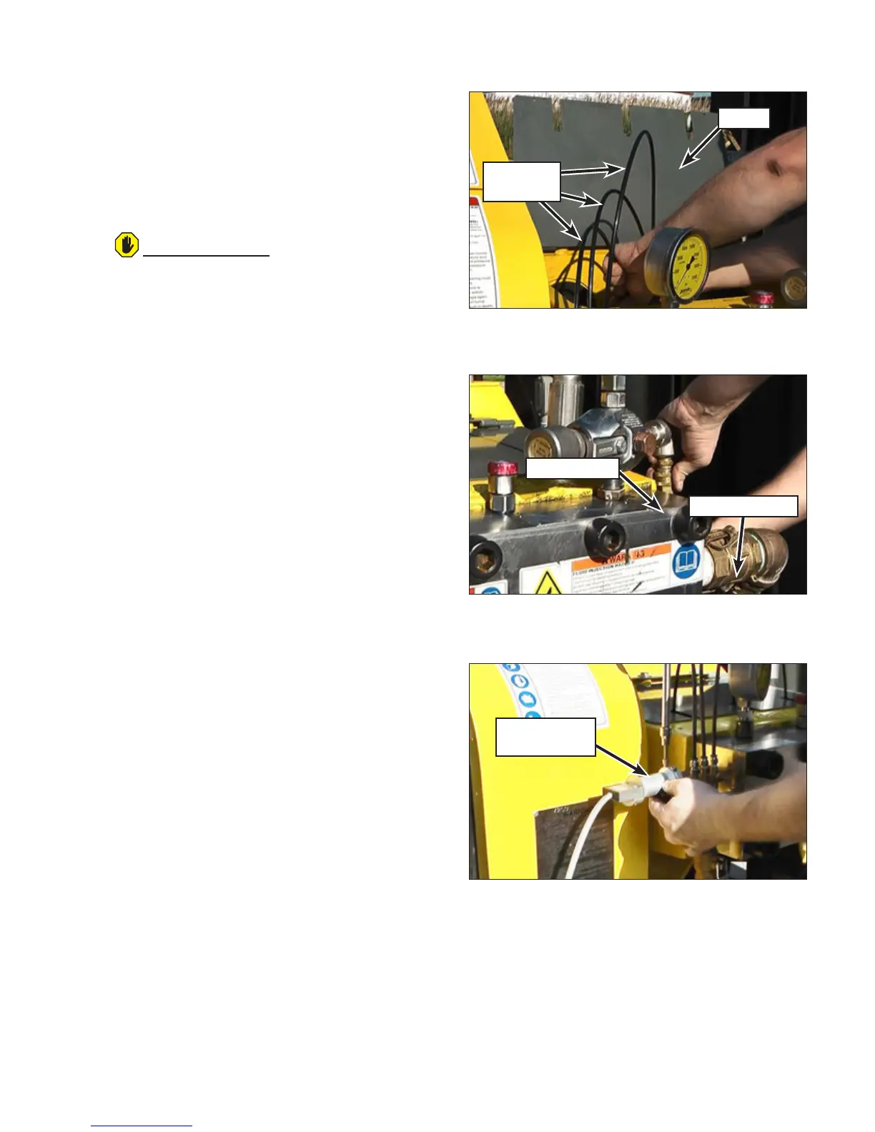
25. Connect the water lubrication lines (Figure 38)
to the ttings on the stufng boxes.
26. Connect the supply coupling (Figure 39) and
the bypass hose to the manifold.
27. Place the hydro-throttle switch and housing
(Figure 40) into position and install the two
bolts that secure it.
28. Verify all connections, glands and bolts were
properly tightened.
29. Ensure the water lubrication system is prop-
erly adjusted, if equipped, before waterblast-
ing. Refer to “Checking the Water Lubrication
System” on page 14 for instructions.
30. If new packing was installed, break in the
packing as outlined in “Breaking in New Pack-
ing” on page 16.
ATTENTION
If converting to a 40K uid end, the secondary
lter must be plumbed for operation. Refer to
“40K Hose Connections”.
When converting to 40K, a charge pump is re-
quired to force the water through the second-
ary lter. If the 40K manifold is not pressurized,
the univalves will be damaged. If your unit is
not equipped with a charge pump, it cannot be
converted to a 40K uid end. Units equipped
with a charge pump are plumbed so that the
charge pump feeds the manifold at all times
with the clutch engaged. The charge pump is
belt driven by the PTO.
Cover
Lubrication
Lines
Figure 38: Connecting the Water Lubrication Lines.
Figure 40: Hydro-Throttle Switch and Housing Installation.
Hydro-Throttle
Switch
Figure 39: Connecting Bypass Hose and Supply Coupling.
Bypass Hose
Supply Coupling