40 41
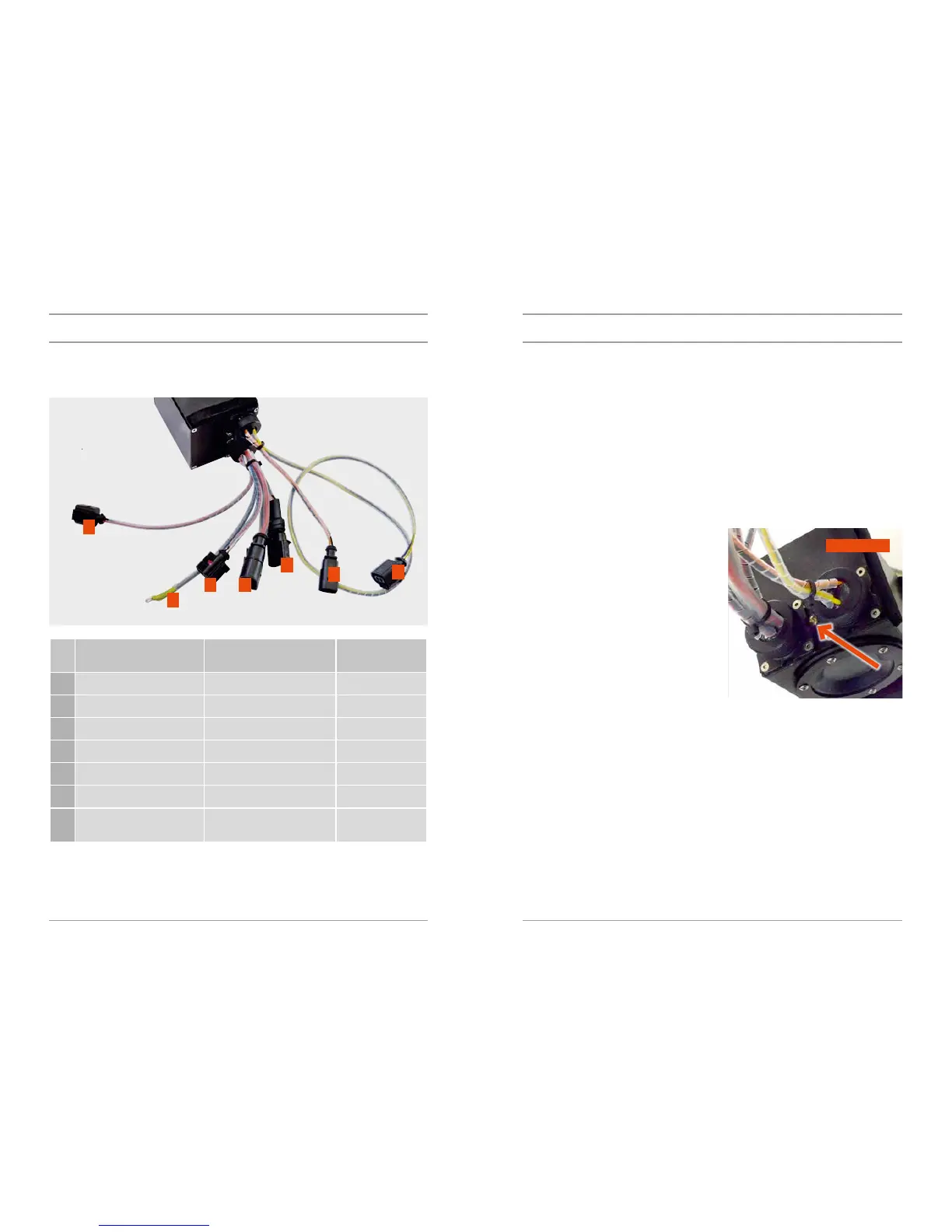
The ignition control unit (ICU) is connected with the other components using these cables.
The numbers of the positions in the table correspond to the numbers in the following gure:
Posi-
tion
Connector type Connector colour Device
1 2-pin female Yellow (+), black (-) Electric bilge pump
2 2-pin male Orange (+), black (-) Ignition coil
3 2-pin male Red (+), black (-) Starter
4 4-pin female Red, white, blue, black Charging
5 2-pin female Red (+), black (-) Control handle
6 3-pin Red (+), black (-), white (sig) Timing sensor
7 Cable eye Black with the yellow and
green end
Ground cable
The electronic ignition system has six basic states:
– POWER OFF, – RIDE,
– POWER ON (ICU DIAGNOSTICS), – ENGINE CLEARING,
– IDLE (INITIAL STATE), – FAULT.
These states are signalised with a two-colour LED situated on the front of ICU between the conductor
bundles.
POWER OFF
In this state the ICU is switched o. The LED is not lit or ashing. The ICU switch-on or engine cleaning
is expected.
POWER ON
You will get into this state from the POWER OFF
state by inserting the engine shut-o key in the
engine shut-o switch on the handle. If the elec-
tric bilge pump is switched on, the battery test is
performed and it waits for the key to be pulled out
of the handle. If the battery voltage is assessed as
low, the unit switches over to the FAULT state (it
signals the fault using the LED and then it switches
over to the POWER OFF state). If the ICU voltage
is sucient for further operation, it is expected
that the key will be pulled out of the handle within
thirty seconds after its inserting. If the key remains
in the handle holder longer than 30 seconds, the
ICU will get into the state FAULT which is signalled
by means of the LED. This fault is signalled until
the key is pulled out of the handle holder, then it
will get to the state POWER OFF.
If the key was pulled out within the time limit of 30 seconds, the control unit gets to the state IDLE
(INITIAL STATE) which is signalled by the LED blinking orange.
IDLE
In the IDLE state (INITIAL STATE), the ICU will switch o both the starter and ignition, the LED slowly
ashes orange. It remains in this state until 5 minutes expires from the moment when the engine
shut-o key was last inserted in the handle or until a request for the engine start is made by inserting
the key in the handle. If the key is not been inserted in the handle for longer than 5 minutes from the
moment when it was inserted last, the ICU gets into the state POWER OFF.
If the key is inserted within 5 minutes from the moment when it was inserted last, the unit will wait
3 seconds and then it gets through the state STARTER (when the electric starter of the combustion
engine and ignition is activated) to the state RIDE.
If the ICU stays in the state IDLE, the water is sucked periodically by means of an electric bilge pump.
5
7
4 3
6
1
2
LED
FIGURE 1
DESCRIPTION OF PARTSDESCRIPTION OF PARTS