54 55
FINS
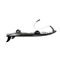
Every JetSurf is supplied with 3 ns - two (2) side ones (small) and one (1) main one (big)..
FASTENING OF SIDE (SMALL) FINS
First unscrew the long screw which is screwed in the n. Slide the side n into the opening in the
bottom side of the board. Make sure that the ns are oriented correctly – FIGURE 1. Find the
opening in the top side of the power board (it is situated nearby the straps, above the n). Insert the
long screw you have screwed out of the side n into the opening – FIGURE 2. Fasten the n
using a cross-head screwdriver PH 2x100 (supplied with the tools). TIGHTEN GENTLY. Please check
whether the n is tightened up, the n should not move..
MAIN FIN FASTENING
Attach the main n from the bottom side of the
power board and attach it with 8 hex-socket
screws M6x8 mm. Tighten the screws in the
criss-cross pattern. When using a two-part n,
you can dismantle only the spike (4 hex-socket
screws M6x8) and leave the platform attached
to the power board. The tightening key is in-
cluding in the tools supplied with the JetSurf.
Check the correct orientation of the n – FIG-
URE 3.
RIDERIDE
|5| RIDE
BEFORE YOU START
Before your rst ride without being supervised by a sales person or a technician of JetSurf, please
make sure that you have read and understood the manual supplied together with the power board.
STAND
Every JetSurf™ is supplied with a light stand. The stand should be used on a solid levelled surface and
it is only used to keep the JetSurf motorized power board in a comfortable height. Use of the JetSurf
stand is strongly recommended to keep the JetSurf motorised power board above the ground, it is
intended as an aid for preparation, maintenance and cleaning of the motorized power board.
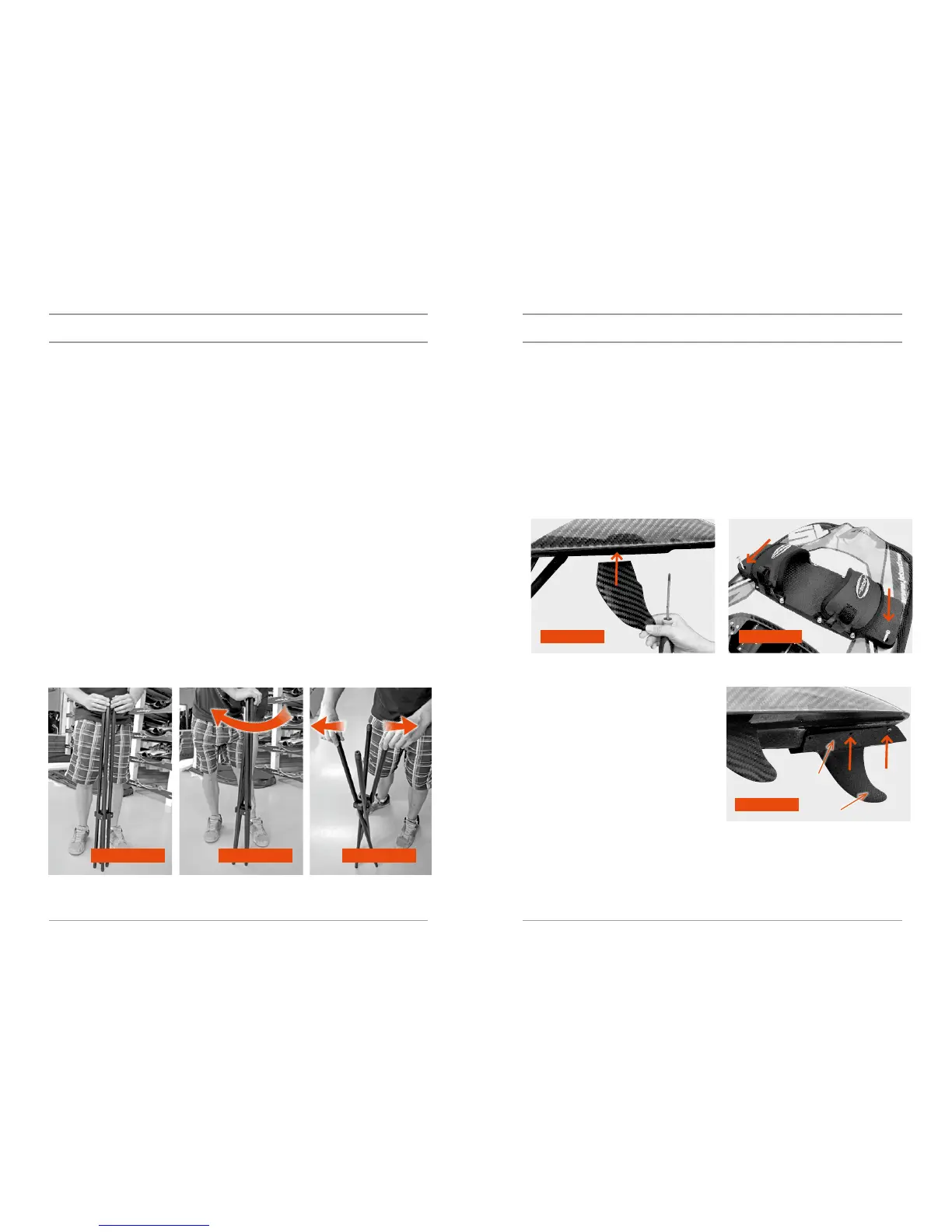
STAND ERECTION
Place all four rods parallel - FIGURE 1. Take the ends of the rods which are farther from the stand
clip and turn them gently clockwise – FIGURE 2. Then take the opposite ends of two rods (the side
where the ends of the rods are closer to the stand clip) and pull these ends apart – FIGURE 3.
Make sure that the stand is situated on the solid surface and that the power boards rests on the
stand correctly (the engine should be directly above the stand and all four rods of the stand touch
the power board).
POWER BOARD
STERN
FIGURE 1 FIGURE 2
FIGURE 3
FIGURE 1 FIGURE 2 FIGURE 3
base
main n