75
JOHNSON CONTROLS
FORM 100.50-EG12 (918)
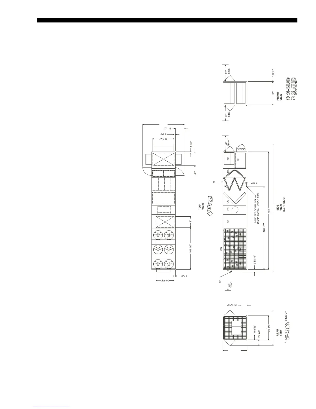
General Arrangement Drawing – 70–80 Ton Models
BOTTOM SUPPLY / BOTTOM RETURN
FIGURE 11 - GENERAL ARRANGEMENT DRAWING
NOTES
1. 10’ Clearance Minimal Over The Top
of the Condensing Unit.
2. Only One Adjacent Wall Can Exceed
Unit Height.
3. 12’ Clearance Required to Adjacent
Units
4. 8’ Service Access Recommended on
One Side.
5. Economizer and Exhaust Hoods,
Where Applicable, are Folded Inside
Unit for Shipment.
SECTION DESCRIPTIONS:
EE = Economizer
FE = Fan Exhaust
MB = Mixing Box
_F = Filter Segments
CC = Cooling Coils
FS = Supply Fan
DP = Discharge Plenum
CO = Condenser Section
CP = Control Panel
LD08128
13’-5”
11’ - 5 13/16” 41’ - 2”
10’
7’ - 8 7/8”

 Loading...


