JOHNSON CONTROLS
58
FORM100.50-EG12 (918)
Electrical Data
ELECTRICAL SERVICE SIZING
In order to determine the electrical service required for the cooling only Series 100 single
package unit, use the appropriate calculations listed below from UL 1995. Based on the
configuration of the single package unit, the calculations will yield different minimum cir-
cuit ampacity (MCA) and maximum overcurrent protection (MOP).
Using the following load definitions and calculations, determine the correct electrical siz-
ing for your unit. All concurrent load conditions must be considered in the calculations, and
you must use the highest value for any combination of loads.
Load Definitions:
• LOAD1 is the current of the largest motor – compressor or fan motor.
• LOAD2 is the sum of the remaining motor currents that may run concurrently with
LOAD1.
• LOAD3 is the current of the electric heaters – zero for cooling only units.
• LOAD4 is the sum of any remaining currents greater than or equal to 1.0 amp.
Use the following calculations to determine MCA and MOP for units supplied with a single-
point power connection:
MCA = (1.25 x LOAD1) + LOAD2 + LOAD3 + LOAD4
MOP = (2.25 x LOAD1) + LOAD2 + LOAD3 + LOAD4
If the MOP does not equal a standard current rating of an overcurrent protective device,
then the marked maximum rating is to be the next lower standard rating. However, if the
device selected for MOP is less than the MCA, then select the lowest standard maximum
fuse size greater than or equal to the MCA.
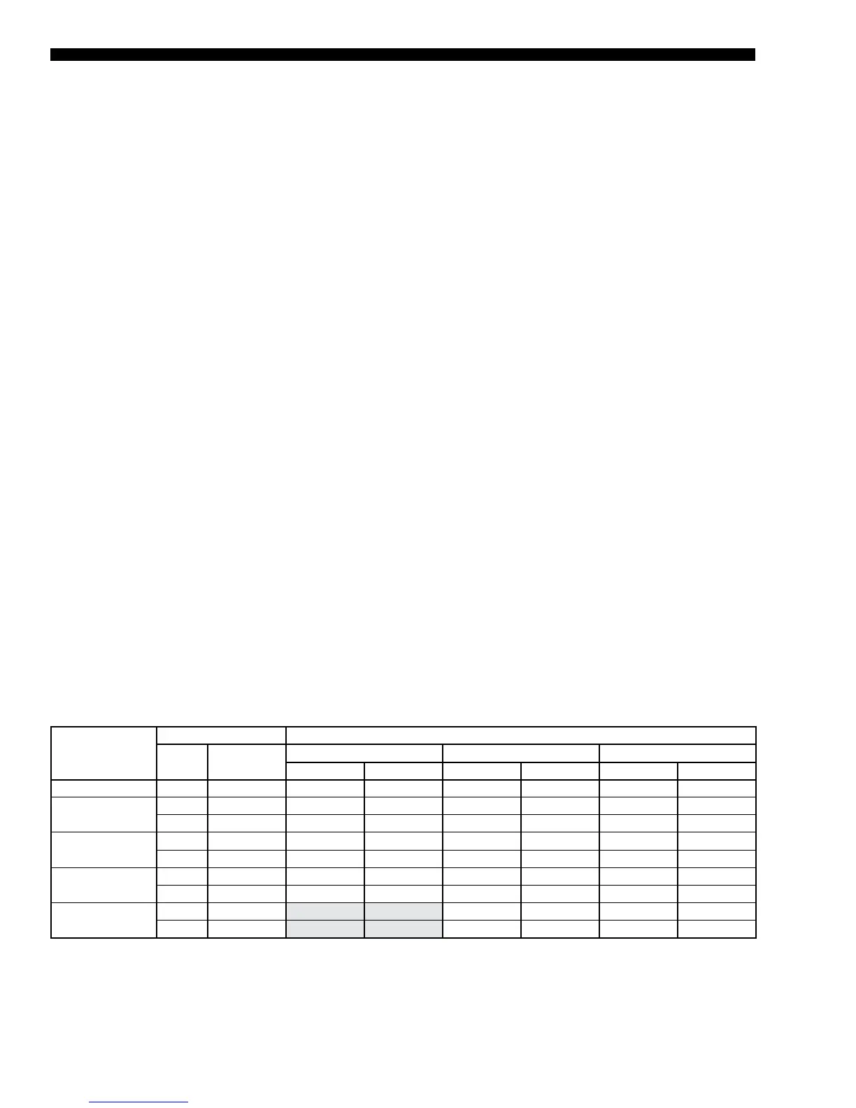
TABLE 27 - COMPRESSOR DATA (R-410A)
MODEL
COMPRESSOR NOMINAL VOLTAGE
QTY MODEL
208/230 460 575
RLA LRA RLA LRA RLA LRA
YPAL 70 TON
6 ZP120 33.3 239 17.9 125 12.8 80
YPAL 75 TON
2 ZP154 51.3 300 23.1 150 19.9 109
4 ZP137 48.1 245 18.6 125 14.7 100
YPAL 80 TON
4 ZP154 51.3 300 23.1 150 19.9 109
2 ZP137 48.1 245 18.6 125 14.7 100
YPAL 90 TON
4 ZP182 55.8 340 26.9 173 23.7 132
2 ZP154 51.3 300 23.1 150 19.9 109
YPAL 105 TON
3 ZP182 26.9 173 23.7 132
3 ZP236 30.8 229 25.0 180
NOTE: *RLA data is per compressor

 Loading...


