89
JOHNSON CONTROLS
FORM 100.50-EG12 (918)
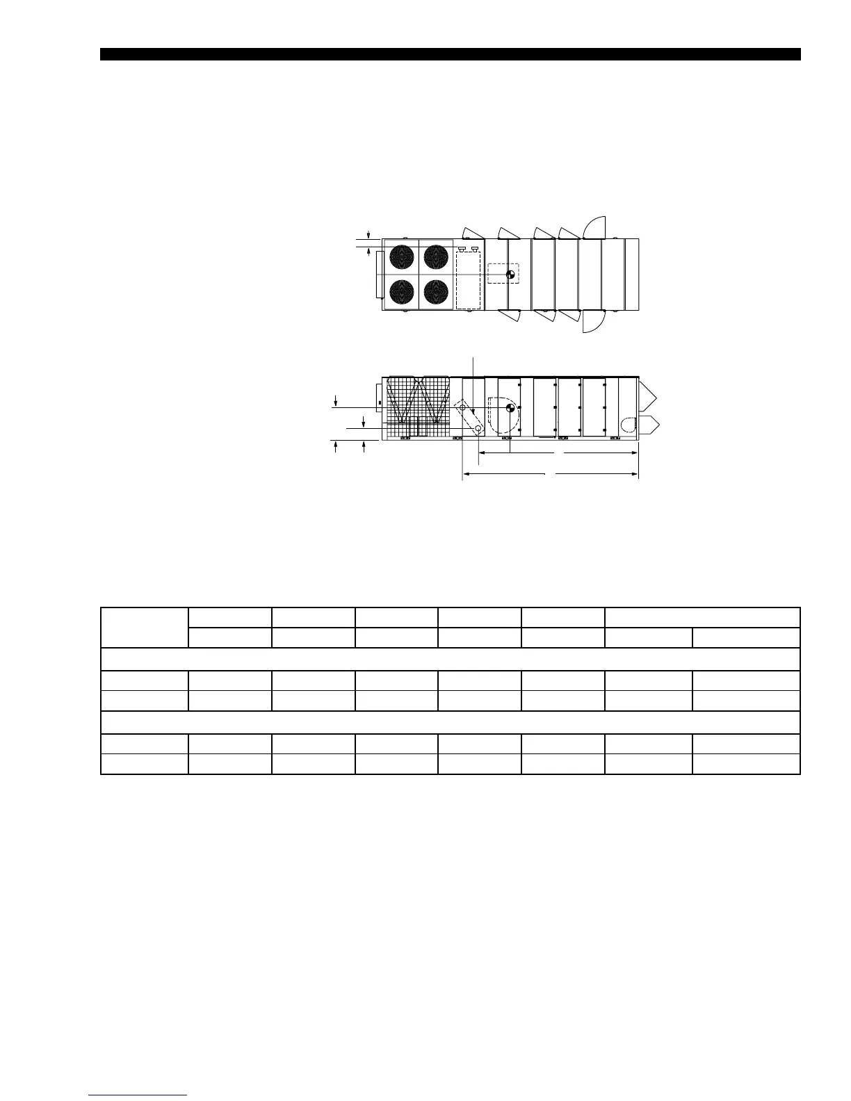
Hot Water/Steam Coil Connection Locations
TABLE 35 - FITTING LOCATION DIMENSIONS
UNIT SIZE
A B C D
SUPPLY
D
RETURN
CONNECTION SIZES (INCHES)
Note 1 Note 2 Note 3 Note 4 Note 4 SUPPLY RETURN
HOT WATER
70–80 254.60 285.60 6.25 45.60 16.00 2-inch FPS 2-inch FPS
90–105 283.10 319.80 6.25 50.10 15.50 2-inch FPS 2-inch FPS
STEAM
70–80 254.60 270.50 5.75 31.90 16.00 2-inch MPT 1.5-inch MPT
90–105 283.10 301.50 5.75 32.60 15.60 2-inch MPT 1.5-inch MPT
NOTES
1. Location of return line connection, horizontal from economizer corner post, in direction of airow
2. Location of supply line connection, horizontal from economizer corner post, in direction of airow
3. Location of both supply and return lines, horizontal from outside casing of unit, across direction of airow
4. Location of supply and return lines, vertical from bottom edge of base rail
MPT = Male Pipe Thread FPS = Female Pipe Sweat FPT = Female Pipe Thread
Hot Water Coil Connections w/ controls are valve connections facing bottom of the unit, at locations indicated.
Steam and Hot Water connections w/o controls are ttings connections facing side of the unit, at locations indicated.
C
D Supply
D Return
From Base Rail Bottom
Piping Connections
A
B
Coil
LD08119
HOT WATER & STEAM
COIL CONNECTION
LOCATIONS

 Loading...


