Network Control Module 300 Series Technical Bulletin 103
nc3power
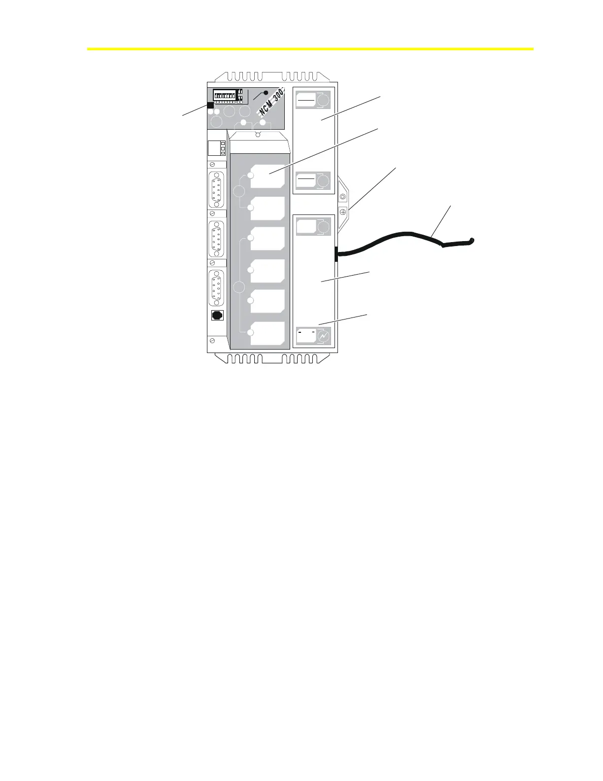
Battery Cover
Power Supply Mounting Screw
Power Cord to Main AC
.
Power Supply
Power conditioning board is
under sheet metal at this end.
ISA Slot Cover
1 2 3 4 5 6 7 8
1
2
3
4
5
6
7
8
I
N
O
U
T
RE
L
OA
D
7
8
P
O
W
E
R
O
N
C
O
N
F
I
G
.
E
N
D
O
F
L
I
N
E
a
b
D
-
R
A
M
-ATTENTION -
PLEASE DISCONNEDT BATTERY
BEFORE INSTALLING MEMORY
B
A
T
T
E
R
Y
NEXT SERVICE DATE:
REF
N2
-
N2
+
a
b
I
S
A
S
L
O
T
S
I
I
I
I
V
C
O
M
M
-
P
O
R
T
S
I
I
I
P
O
W
E
R
S
U
P
P
L
Y
DISCONNECT
POWER BEFORE
SERVICING
DANGER
LINE VOLT AGE
INSIDE
Battery Fault
(LED)
Figure 41: Location of Power Supply Components
Removal of Power Supply
It may be easier to remove the power supply when the ISA slot cover
is removed.
To remove the power supply:
1. Turn off main AC power.
2. Disconnect the NCM AC cord from the power box (not from the
NCM end).
3. Remove the power supply mounting screw from the NCM base.
4. Slide the power supply assembly down (away from the battery
cover) approximately 1/4 inch to disengage it from the NCM base.
5. Lift power supply up approximately one inch to gain access to the
power conditioning board. See Figure 42.
6. Disconnect the power conditioning board from the P6 connector on
the NCM board by pulling up firmly on its outer edges.

 Loading...


