Network Control Module 300 Series Technical Bulletin 102
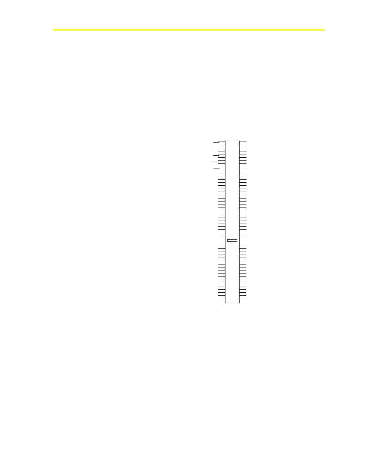
Probing ISA Slot Pins
1. Remove the ISA slot cover.
2. With a volt meter, measure voltages between the following pins:
+12 V and ground (tolerance 11.4 V/12.6 V)
-12 V and ground (tolerance -11.4 V/-12.6 V)
+5 V and ground (tolerance 4.875 V/5.25 V)
-5 V and ground (tolerance -4.5 V/-5.5 V)
The location of these pins is shown in Figure 40.
98
97
96
95
94
93
92
91
90
89
88
87
86
85
84
83
82
81
80
79
78
77
76
75
74
73
72
71
70
69
68
1
2
3
4
5
6
7
8
9
10
11
12
13
14
15
16
17
18
19
20
21
22
23
24
25
26
27
28
29
30
31
67
66
65
64
63
62
61
60
59
58
57
56
55
54
53
52
51
50
32
33
34
35
36
37
38
39
40
41
42
43
44
45
46
47
48
49
Ground
+5V
-5V
-12V
+12V
isapins
Figure 40: Location of ISA Slot Pins
If any one of these tests fail, replace the power supply and/or NCM.
Replacing the Power Supply
Figure 41 shows the location of components for removal and
installation of the power supply. Figure 42 shows the power supply
cover lifted to gain access to the P6 connector and power conditioning
board.
Note: The power supplies of the NCM311 and NCM361 are not
field replaceable to meet European Electrical Safety Codes, which
apply in all European Union countries.

 Loading...