Network Control Module 300 Series Technical Bulletin 104
1 2 3 4 5 6 7 8
1
2
3
4
5
6
7
8
I
N
O
U
T
7
8
P
O
W
E
R
C
O
N
F
I
G
.
E
N
D
O
FL
I
N
E
D
-
R
A
M
-ATTENTION -
PLEASE DISC ONNEDT BAT TERY
BEFORE INSTALLING MEMORY
B
A
T
T
E
R
Y
NE XT SE R V I C E DA T E :
a
b
I
S
A
S
L
O
T
S
I
I
I
IV
C
O
M
M
-
P
O
R
T
S
II
I
P
O
W
E
R
S
U
P
P
L
Y
DISCONNECT
POWER BEFO RE
SERVICIN G
DANGER
LINE V OLTAGE
INSIDE
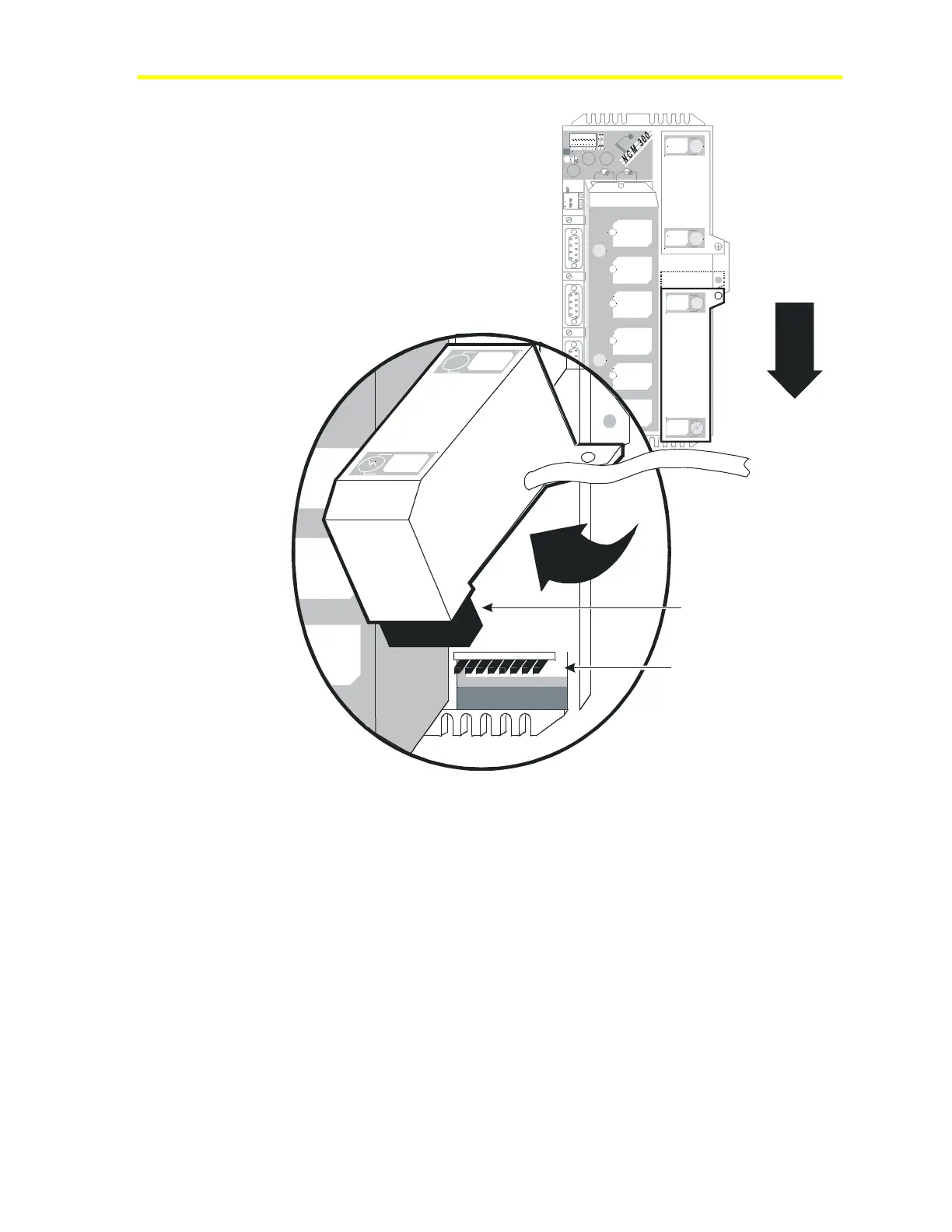
Remove screw,
slide down.
Lift Up
p6conctr
B
A
TT
E
R
Y
NEXT SERVICE DATE:
Power
P6
Connector
Power
Conditioning
Board
Figure 42: P6 Connector and Power Conditioning Board
Installation of Power Supply
To install the power supply:
1. Connect the power conditioning board to the P6 connector on the
NCM board. See Figure 42.
2. Line up the power supply sheet metal in slots in the NCM base
sheet metal and engage by sliding up toward the battery cover.
Note: Be careful not to pinch any wires.
3. Install the power supply mounting screw.
4. Reconnect the AC cord to the power box.
5. Turn on main AC.

 Loading...


