Network Control Module 300 Series Technical Bulletin 79
Installing the MIB-OWS Board
The steps below detail how to install the MIB-OWS into the
Fire-Net NCM.
1. Unplug the Fire-Net NCM from any power source.
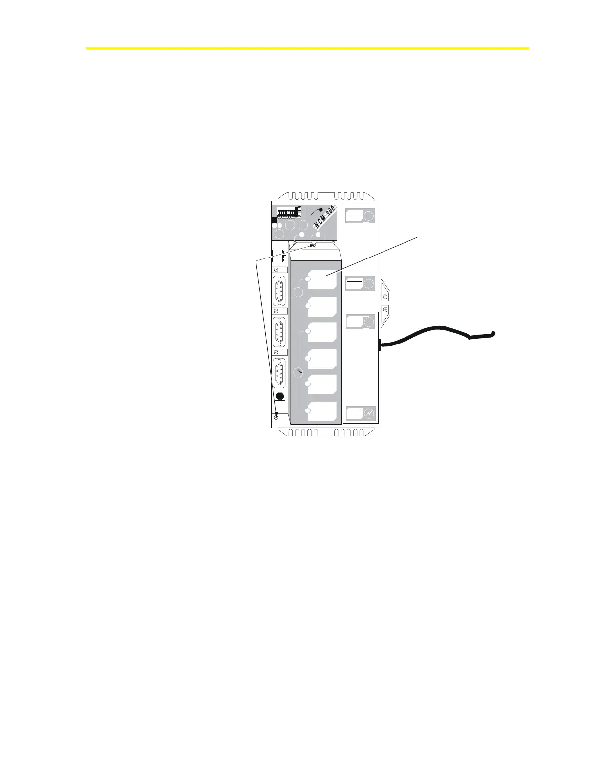
2. Remove the ISA slot cover by loosening the two screws that hold
the cover on the Fire-Net NCM board (Figure 25). The remaining
ISA slot is exposed.
nc2srw
ISA Slot Cover
1 2 3 4 5 6 7 8
1
2
3
4
5
6
7
8
I
N
O
U
T
R
E
L
O
A
D
7
8
P
O
W
E
R
O
N
C
O
N
F
I
G
.
E
N
D
O
F
L
I
N
E
A
B
D
-
R
A
M
-ATTENTION -
PLEA SE D ISC ONNED T BATT ERY
BEFORE INS TALLING MEMORY
B
A
T
T
E
R
Y
NEXT SERVICE DATE:
REF
N2
-
N2
+
P
O
W
E
R
S
U
P
P
L
Y
DISCONNECT
POWER BEFORE
SERVICING
DANGER
LINE VOLTAGE
INSIDE
Remove
these two
screws.
A
B
I
S
A
SLO
T
S
I
I
I
I
V
POR
T
S
I
I
I
Figure 25: Removing the ISA Cover
Note: The MIB-OWS is a two-tiered board that plugs into one ISA
slot and hangs over into the remaining space. Remove the two metal
tabs on the Fire-Net NCM so the MIB-OWS fits.
3. Twist out the two metal tabs that cover the ISA slot and other
empty slot (Figure 26) if not already removed.