341849-YIM-A-0108
14 Johnson Controls Unitary Products
HEAT PUMP SAFETY SWITCH OPERATION
If the unit is equipped with the field installed upgrade
safety package, the refrigeration system will be pro-
tected against high or low refrigerant pressure and low
indoor coil temperature. If any of these three safety
switches opens, the unit will be shut off for the 5 minute
anti-short cycle time. Once this has expired, a six hour
elapsed run timer begins. If a second opening of a
safety switch occurs during this six hour period, the
compressor will be locked out.
Resetting the lockout function is accomplished by;
1. Removing power from the control's thermostat 1st
stage (Y) input for a time not to exceed 5 seconds
(ON-OFF-ON).
2. Removing power from “R” for more than 2 sec-
onds.
3. Shorting the “TEST” pins together for more than 2
seconds.
ELECTRIC HEAT LIMIT SWITCH OPERATION
The limit switch responds to over temperature condi-
tions in the air duct. Opening of the device results in
dropping power to the relays. The control logic will also
respond by turning off the relays. After four limit cycle
trips the unit goes into a 1 hour soft lockout period. If
during this period the control “sees” another limit cycle,
the unit will go into a hard lockout condition. Once in a
hard lockout state, the fan is locked on and the heaters
are disabled. Only a power cycle will clear the state.
During the soft lockout period, the fan responds to
thermostat input but the heaters are enabled. This is
to sense a failed heater relay. The limit cycle count is
reset at the start of a heat request. If the limit
remains open for period of 80 seconds or more, the
control is immediately put into a hard lockout condi-
tion. Only a power cycle will clear this state.
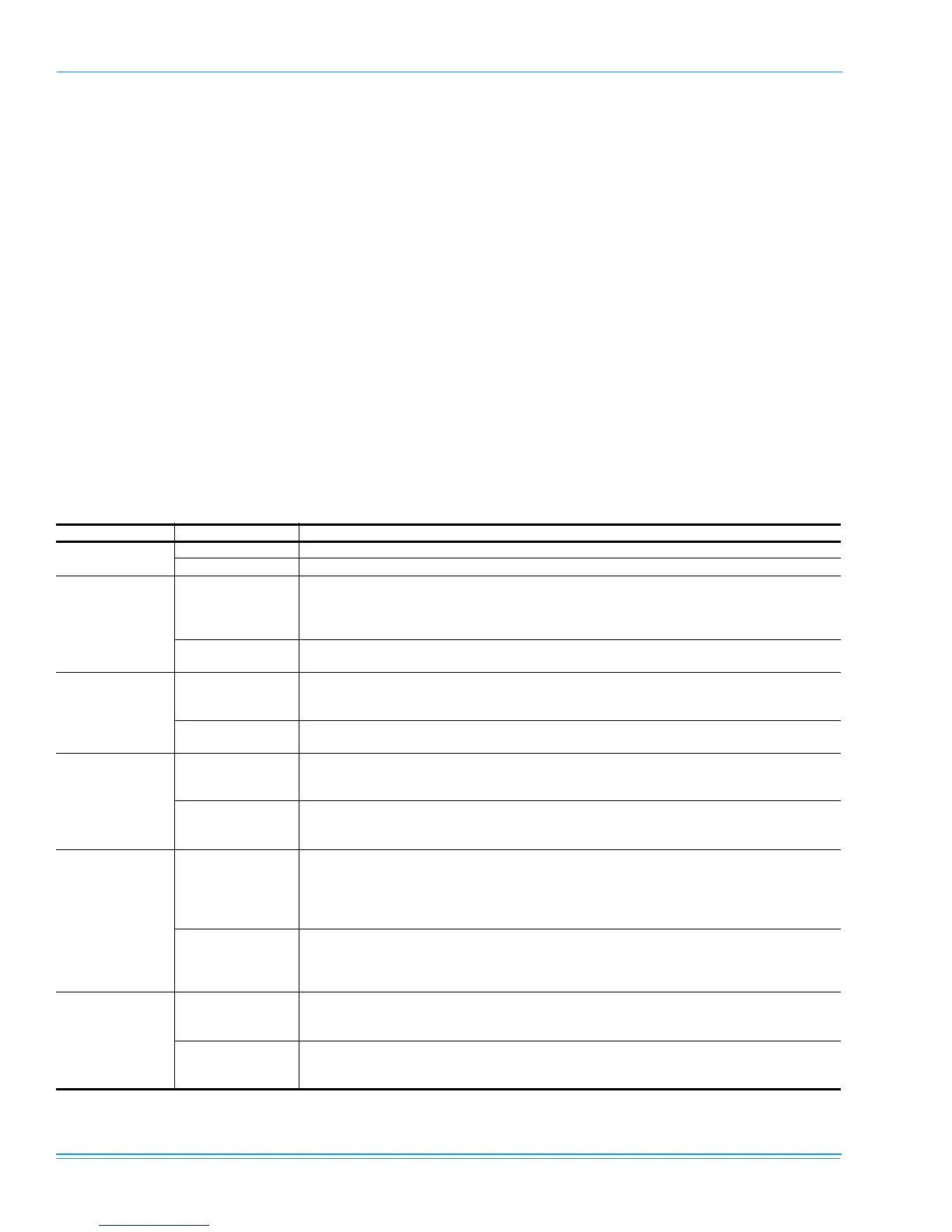
TABLE 17: Thermostat Signals (Three Phase Units)
SIGNAL STATE BOARD FUNCTION
“G”
ON FAN INSTANT ON
OFF FAN INSTANT OFF
“G” & “Y” & “O”
ON
FAN INSTANT ON
COMPRESSOR AND OUTDOOR FAN INSTANT ON (AFTER ANTI-SHORT CYCLE DELAY)
REVERSING VALVE ENERGIZED
SYSTEM OPERATES IN COOLING
OFF
COMPRESSOR AND OUTDOOR FAN INSTANT OFF
FAN 60 SEC. DELAY OFF
“G” & “Y”
ON
FAN INSTANT ON
COMPRESSOR AND OUTDOOR FAN INSTANT ON (AFTER ANTI-SHORT CYCLE DELAY)
SYSTEM OPERATES IN HEATING
OFF
COMPRESSOR AND OUTDOOR FAN INSTANT OFF
FAN 60 SEC. DELAY OFF
“G” & “W”
ON
FAN INSTANT ON
HEATER BANK 1, 2 & 3 ELEC. HEAT INSTANT ON
HEATER BANK 4, 5 & 6 ELEC. HEAT 10 SEC. DELAY ON
OFF
HEATER BANK 4, 5 & 6 ELEC. HEAT INSTANT OFF
HEATER BANK 1, 2 & 3 ELEC. HEAT 1/2 SEC. DELAY OFF
FAN 10 SEC. DELAY OFF
“G” & “Y” & “W”
ON
FAN INSTANT ON
COMPRESSOR AND OUTDOOR FAN INSTANT ON
SYSTEM OPERATES IN HEATING
HEATER BANK 1, 2 & 3 ELEC. HEAT INSTANT ON
HEATER BANK 4, 5 & 6 ELEC. HEAT 10 SEC. DELAY ON
OFF
COMPRESSOR AND OUTDOOR FAN INSTANT OFF
HEATER BANK 4, 5 & 6 ELEC. HEAT INSTANT OFF
HEATER BANK 1, 2 & 3 ELEC. HEAT 1/2 SEC. DELAY OFF
FAN 60 SEC. DELAY OFF
“W”
ON
FAN INSTANT ON
HEATER BANK 1, 2 & 3 ELEC. HEAT INSTANT ON
HEATER BANK 4, 5 & 6 ELEC. HEAT 10 SEC. DELAY ON
OFF
HEATER BANK 4, 5 & 6 ELEC. HEAT INSTANT OFF
HEATER BANK 1, 2 & 3 ELEC. HEAT 1/2 SEC. DELAY OFF
FAN 10 SEC. DELAY OFF