341849-YIM-A-0108
6 Johnson Controls Unitary Products
COMPRESSORS
Units are shipped with compressor mountings factory-
adjusted for shipping.
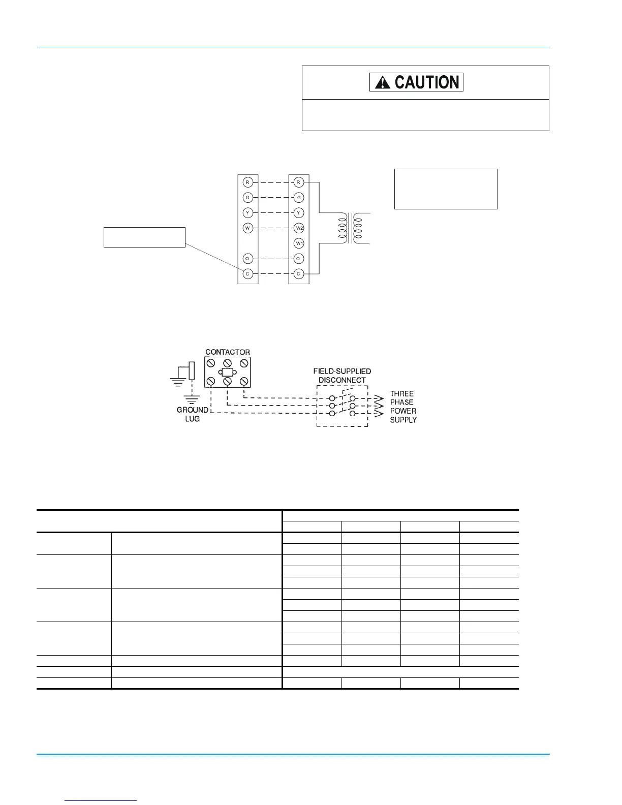
FIGURE 2 - Typical Field Wiring DIagram
Loosen compressor bolts half turn before
operating unit.
POWER WIRING
24 VOLT TRANSFORMER
UNIT TERMINAL STRIP
THERMOSTAT
CAUTION: Label all wires prior to disconnection when servicing controls. Wiring errors can
cause improper and dangerous operation. Verify proper operation after servicing.
** = Minimum wire size of 18 AWG
wire should be used for all field
installed 24 volt wire.
**
* = Only required on units with
supplemental electric heat.
*
CONTROL WIRING
NOTE:
HEAT ANTICIPATOR
SHOULD BE SET AT 0.25
AMPS FOR ALL MODELS.
PROGRAMMABLE
THERMOSTAT ONLY
REFER TO ELECTRICAL DATA
TABLES TO SIZE THE
DISCONNECT SWITCH,
WIRING & OVERCURRENT
PROTECTION.
TABLE 3: Physical Data
Models
BHA
036 042 048 060
Indoor
Blower
Centrifugal Blower (Dia. X Wd. In.)
Fan Motor Hp
10 x 8 11 x 10 11 x 10 11 x 10
3/4 3/4 3/4 1
Indoor
Coil
Rows Deep
Fins Per Inch
Face Area (Sq. Ft.)
3333
15 15 16 16
4.38 4.38 5.62 5.62
Outdoor
Fan
Propeller Dia. (In.)
Fan Motor Hp
Nom. CFM Total
22 22 22 22
1/41/41/41/4
2,400 2,400 2,800 2,800
Outdoor
Coil
Rows Deep
Fins Per Inch
Face Area (Sq. Ft.)
1111
20 20 16 20
11.7 11.7 16.4 16.4
Charge Refrigerant 22 (Lbs./oz.) 5/5 6/0 9/0 10/0
Filter Face Area (Sq. Ft./qty./size) 4.28/2/14" x 22"
Compressor Hermetic Type, (Qty. = 1) Scroll Recip. Scroll Scroll