Wired Controller DWUNI User Manual
24
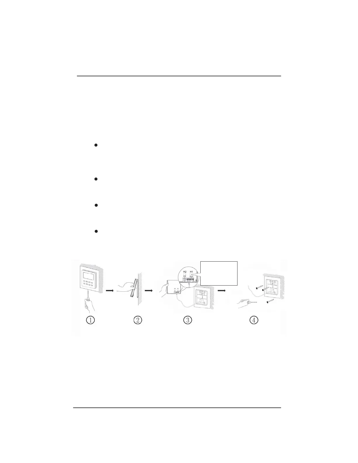
4.4 Disassembly
Fig. 24 Disassembly diagram for wired controller
No need to set the wire of wired controller into the clasp.
If the air conditioning unit is installed where it is vulnerable to electromagnetic
interference,then the signal and communication lines of the wired controller
must be
a shielded twisted pair.
The 4-pin terminal connects to the indoor unit, while the 2-pin terminal
connects to a central controller or additional wired controller. The connecting method
for the 2-core connection wire is same as that of 4-core connection wire.
(3) Stick the soleplate of wired controller on the wall and then use screw M4×25 to
attach soleplate and installation hole on wall together;
(4) Insert the four-conductor twisted pair line into the slot of the wired controller and
then snap
the front panel and the soleplate of the wired controller together.
(5) Block the four-core wire into the groove at the left side of wiring column; bundle
the front panel of wired controller to its soleplate.
Note:
Separate the signal and communication lines of the wired controller from the
power cord and connection lines between the indoor and outdoor unit, with a
minimum interval of 8 inches, otherwise the communication of the unit may work
abnormally due to interference.
Connect to either H1
terminal or H2 terminal.
As to which terminal
should be connected,
it depends.
© 2018 Johnson Controls, Inc.
LIT-12012504
Issued June 2018