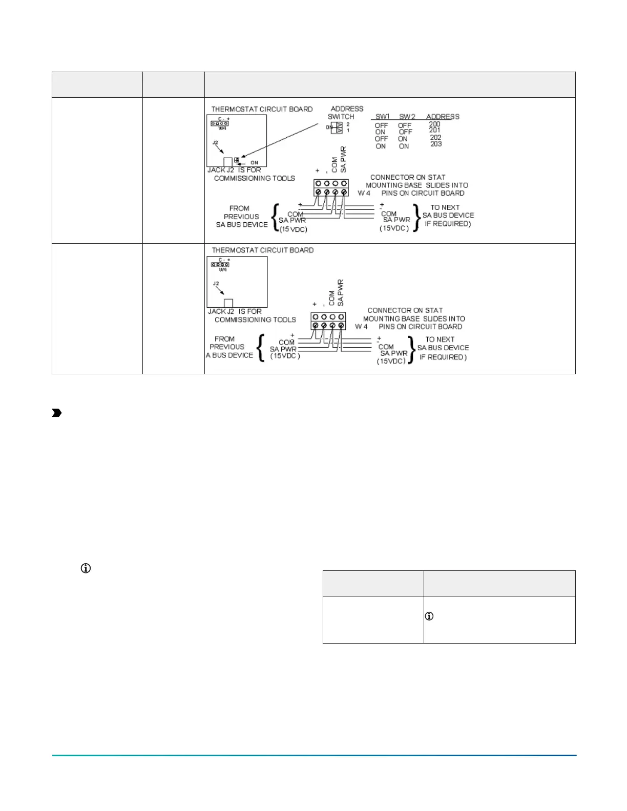
Table 8: Termination details
Type of Field Device Type of Input/
Output
Termination diagrams
Network Stat
with Terminals
Addressable
SA Bus
Network Stat with
Terminals (Fixed
Address = 199)
SA Bus
Setup and adjustments
Important: Electrostatic discharge can damage
controller components. Use proper electrostatic
discharge precautions during installation, setup, and
servicing to avoid damaging the controller.
Configuring wireless communications
(CVM models only)
About this task:
To configure a controller for use with the ZFR Pro Series
Wireless Field Bus system, complete the following steps:
1. Disconnect the 24 VAC supply from the controller.
2. Wire the input/output terminals and SA Bus.
Note: In wireless network applications, do
not connect any wires to the FC Bus terminal
block. (Connect the SA/FC terminal block on
an expansion module to an SA Bus only.)
3. Important: Before the CVM controller is powered
on, connect the ZFR Pro Wireless Field Bus Router
to the FC Bus port (RJ-12 modular jack) on the front
of the controller.
4. Ensure that the controller's rotary switches are
set to the correct device address. For details about
setting a device address, see .
5. Reconnect the 24 VAC supply to the controller.
Result
For more information about the FX-ZFR 1800 Wireless
Field Bus system, refer to the FX-ZFR Series Wireless Field
Bus System Bulletin (LIT-12011660). For more information
on the FX-ZFR Pro Wireless Field Bus system, refer to the
WNC1800/FX-ZFR182x Pro Series Wireless Field Bus System
Bulletin (LIT-12012378).
Setting the device address on CGM
models
The CGM controllers are manager devices on MS/TP (FC
or SA) Buses. Before you operate controllers on a bus,
you must set a valid and unique device address for each
controller on the bus.
The following table describes the valid rotary switch
device addresses for communications bus applications.
FC Bus communication
mode
Valid device address range
Wired MS/TP
communication
4-127
Note: Addresses 0-3 are
reserved and not for use on
equipment controllers.
The device address is a decimal address set using three
rotary switches located at the top of the controller. The
numbers are ordered from left to right, most significant
bit (MSB) to least significant bit (LSB) when the controller
is oriented. . In the following figure, the switches are set
to 1 2 3, designating this controller's device address as
123.
F4-CV Series VAV Terminal Equipment Controllers Installation Guide14