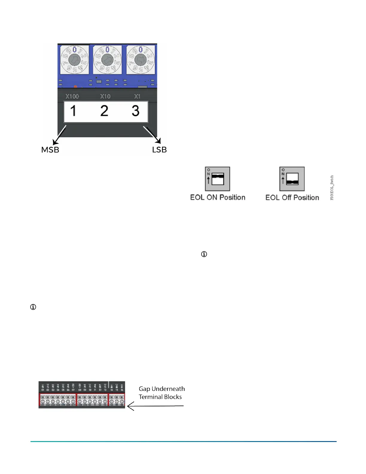
Figure 12: Rotary switch block
The device address must match the device address
defined in the Controller Configuration Tool (CCT) under
Define Hardware > Network Settings.
To set the device addresses on controllers, complete the
following steps:
1. Set a unique and sequential device address for each
of the devices connected on the FC or SA, starting
with device address 4.
2. To ensure the best bus performance, set sequential
device addresses with no gaps in the device address
range (4, 5, 6, 7, 8, 9, and so on). The devices do not
need to be physically connected on the bus in their
numerical device address order.
3. Write each controller's device address on the white
label below the Device Address Rotary Switch Block
on the controller's cover.
Removing a terminal block
About this task:
To remove a terminal block from the circuit board,
complete the following steps:
Note: You need a flat blade screwdriver to remove
the terminal block.
1. To prevent any possibility of damage from an
accidental short, remove power from the
controller.
2. Underneath the terminal block, in the small gap
between the bottom of the terminal block and
the circuit board, insert the flat blade of the
screwdriver.
Figure 13: Terminal block
3. To detach the left-hand side of the terminal block,
position the flat blade underneath the terminal
block to the left, and push down the screwdriver
handle. When you do this, you are using the
screwdriver as a lever to pry up the terminal block.
4. To detach the right-hand side of the terminal block,
position the flat blade underneath the terminal
block to the right, and push down the screwdriver
handle.
5. If necessary, repeat steps 3 and 4 until the terminal
block is removed.
Setting the End-of-Line (EOL) switch
(CVM models only)
Each CVM controller has an EOL switch, which, when
set to ON (up), sets the CVM controller as a terminating
device on the bus. See Physical features for the EOL switch
location. The default EOL switch position is OFF (down).
Figure 14: End-of-Line Switch Positions
To set the EOL switch on a CVM controller, complete the
following steps:
1. Determine the physical location of the controller on
the FC Bus.
2. Determine if the controller must be set as a
terminating device on the bus.
Note: For detailed information about EOL
termination rules and EOL switch settings on FC
Buses, refer to the FX MS/TP Communications Bus
Technical Bulletin (LIT-12011670).
3. If the controller is a terminating device on the FC
Bus, set the EOL switch to ON. If the controller is not
a terminating device on the bus, set the EOL switch
to OFF.
When a controller is connected to power with its EOL
switch set to ON, the amber EOL LED on the controller
cover is illuminated.
Input and output wiring validation
The controllers ship with a cooling only, warm or cool
adjust application loaded by default. You can use this
default application to perform wiring verification using
the MAP Gateway, FX-DLK03050, or the FX-DIS1710-0 local
controller display.
To perform wiring validation, ensure that you set the
rotary switches to the desired address or controller
number and wire the input and output terminals. Apply
power to the controller. The Fault LED behaves the same
as it does during normal application load. When the Fault
LED turns off, connect to the device with either a MAP
Gateway, FX-DLK03050, or FX-DIS1710-0 Local Display to
view the points in the controller.
F4-CV Series VAV Terminal Equipment Controllers Installation Guide 15