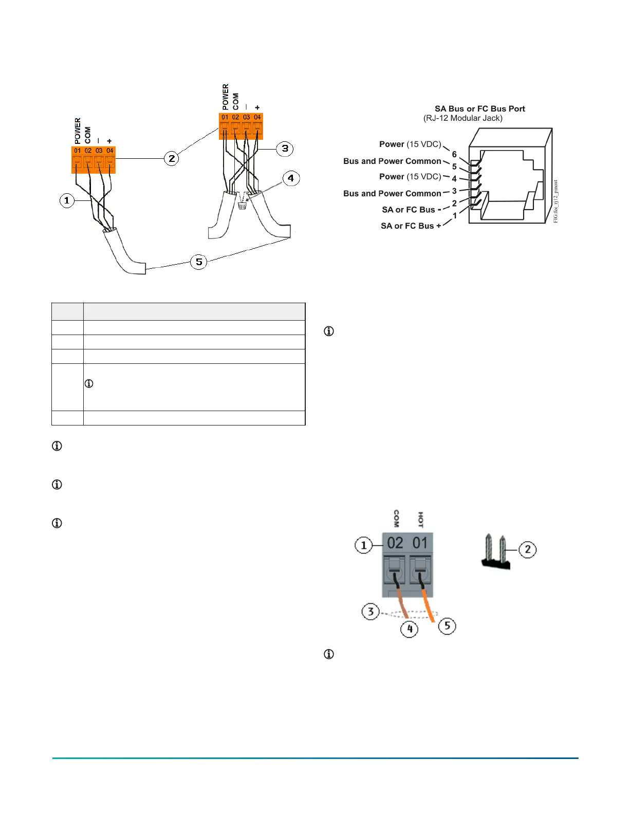
Figure 7: SA Bus terminal block wiring
Table 3: SA Bus configuration
Description
1 Wiring for a terminating device on SA Bus
2 SA Bus terminal blocks
3 Wiring for a daisy chained device on SA Bus
4 Cable shield connection
Note: Connect the shields to ensure they are
continuous the entire length with only one ground
location.
5 Connects to the next device on the SA Bus
Note: Stranded, 4-wire (2 twisted pair) shielded
cable. One twisted pair is the + and - leads. The
second pair is COM and POWER.
Note: Do not use the modular SA Bus port and the
terminal block SA Bus simultaneously. Only use one
of these connections at a time.
Note: The CVM/CVE controller is the EOL for the SA
Bus.
Modular ports
The modular SA and FC bus ports on the face of the CVM
(Figure 8) are RJ-12 (6-position) modular jacks as shown in
Figure 8.
The modular SA Bus port provides a connection for the
MAP Gateway, VAV Balancing Tool, FX- DIS1710 Local
Controller Display, WRZ78xx Series One-to-One Wireless
Transmitter, and NS Series sensors.
Figure 8: Pin number assignments for FC bus and SA
ports on equipment controllers
The modular SA Bus port provides a connection for the
MAP Gateway, ATV7003 VAV Balancing Tool , FX-DIS1710
Local Controller Display, FX-WRZ78xx Series One-to-One
Wireless Transmitter, and NS Series sensors. The modular
FC Bus port provides a connection for the Bluetooth
Commissioning Converter and the FX-ZFR Wireless Router.
Note: Do not use the modular SA Bus port and the
terminal block SA Bus simultaneously. Only use one
of these connections at a time.
Supply power terminal block
The 24 VAC supply power terminal block is a gray,
removable, 2-pin terminal block that fits into a board-
mounted pin header on the upper left of the controller.
Wire the 24 VAC supply power wires from the transformer
to the HOT and COM terminals on the terminal block as
shown in Figure 9. For more information about Supply
Power terminal functions, requirements, and ratings, see
Table 7.
Figure 9: 24 VAC supply power terminal block wiring
Note: The order of the HOT and COM terminals on
the CV series controllers is reversed from the order
of the terminals on the CG series controllers.
F4-CV Series VAV Terminal Equipment Controllers Installation Guide6