Mounting
Observe the following guidelines when mounting a CVM/
CVE controller:
• Ensure that the mounting surface can support the
controller and any user-supplied enclosure.
• Mount the controller on a hard, even surface whenever
possible.
• Use shims or washers to mount the controller securely
and evenly on the mounting surface.
• Mount the controller in an area free of corrosive vapors
that matches the ambient conditions specified in the
Technical specifications section.
• Provide sufficient space around the controller for cable
and wire connections and adequate ventilation through
the controller (at least 50 mm [2 in.] on the top, bottom,
sides, and front of the controllers).
• Do not mount the controller in areas where
electromagnetic emissions from other devices or wiring
can interfere with controller communication.
• Avoid mounting the controller on surfaces with
excessive vibration.
Important: When the air supply to the VAV box is
below 10°C (50°F), make sure that any condensation
on the VAV box, particularly on the damper shaft,
does not enter the controller electronics. Mount
the controller vertically above the damper shaft to
allow any shaft condensation to fall away from the
controller. Additional measures may be required in
some installations.
On panel or enclosure mount applications, observe these
additional guidelines:
• Do not install the controller in an airtight enclosure.
• Mount the controller so that the enclosure walls do
not obstruct cover removal or ventilation through the
controller.
• Mount the controller so that the power transformer
and other devices do not radiate excessive heat to the
controller.
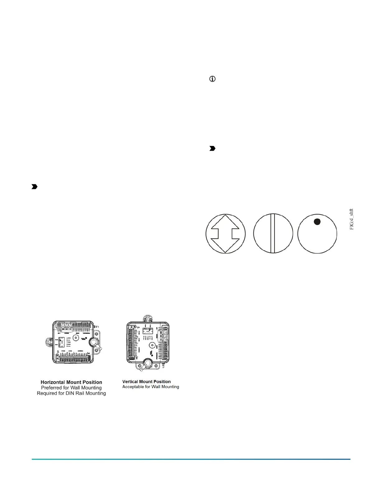
Figure 4: Controller mounting positions
To mount the CVM/CVE controllers, complete the
following steps:
1. Set all the switches on the equipment controller to
their known settings.
2. Place the controller in the proper mounting position
on the damper shaft so that the wiring connections
are easily accessible. Make sure the controller base is
parallel to the VAV box (perpendicular to the damper
shaft). If needed, use a spacer to offset tipping of the
controller caused by the shaft bushings.
Note: Use the alignment marks to center the
captive spacer to ensure sufficient CVM/CVE
movement in either direction.
3. Secure the self-drilling No.10 screw through the
captive spacer with a power screwdriver and 100mm
(4in.) extension socket. Otherwise, use a punch to
mark the position of the shoulder washer, and then
drill a hole into the VAV box using a 3.5mm (9/64in.)
drill bit. Insert the mounting screw and tighten
against the spacer.
Important: Do not overtighten the screw, or
the threads may strip. If mounting to the VAV
box, make sure the screws do not interfere with
damper blade movement.
4. Locate the damper position using the typical
marking on the end of the damper shaft as shown in
the figure below.
Figure 5: Typical damper end shaft icons
5. Note the direction, clockwise (CW) or
counterclockwise (CCW), required to close the
damper. Grasp the damper shaft firmly with pliers,
and either manually close the damper for 90° boxes
or manually open the damper for 45° or 60° boxes.
6. Push down and hold the Manual Override button
and turn the controller coupler until it contacts the
mechanical end-stop at either the full-closed (90°
boxes) or full-open (45° and 60° boxes) position.
7. If the damper for a 90° box closes CCW, rotate the
coupler to the CCW mechanical limit. If the damper
for a 90° box closes CW, rotate the coupler to the CW
mechanical limit. The open end-stop is automatically
set for 90° boxes. For 45° and 60° boxes, you must
provide hard stops at both full-closed and full-open
damper positions. If you install the controller at the
full-open position, the controller provides the open
stop for 45° and 60° boxes. The closed damper seal
provides the full-closed stop.
F4-CV Series VAV Terminal Equipment Controllers Installation Guide 3