Table 1: Physical features
Physical feature: description and references
8 SA Bus Terminal Block (see SA bus terminal block)
9
Sensor Port: (SA Bus) RJ-12 6-Pin Modular Jack (see SA Bus
port )
10
Binary Input (BI) Terminal Block: Dry Contact Maintained
or Pulse Counter/Accumulator Mode (see Terminal wiring
guidelines, functions, ratings, and requirements
11
Universal Inputs (UI) Terminal Block: Can be defined as
Voltage Analog Input (0–10 VDC), Current Analog Input
(4–20 mA), Resistive Analog Inputs (0–600k ohms), or
Dry Contact Binary Input (see Input and Output wiring
guidelines)
12
End-of-Line (EOL) Switch (see Setting the End-of-Line
(EOL) switch)
13 LED Status Indicators (see Table 7)
14 FC Bus Port (RJ-12 6-pin Modular Jack)
Mounting
Observe the following guidelines when mounting a
field controller:
• Ensure the mounting surface can support the
controller, DIN rail, and any user-supplied
enclosure.
• Mount the controller horizontally on 35 mm DIN
rail whenever possible.
• Mount the controller in the correct mounting
position (Figure 2).
• Whenever possible in wall-mount applications,
mount the controller on a hard, even surface.
• Use shims or washers to mount the controller
securely and evenly on the mounting surface.
• Mount the controller in an area free of corrosive
vapors and observe the ambient conditions
requirements in Technical specifications.
• Provide sufficient space around the controller for
cable and wire connections, easy cover removal,
and good ventilation through the controller (50
mm [2 in.] minimum on the top, bottom, and
front of the controller).
• Do not mount the controller on surfaces prone to
vibration, such as ductwork.
• Do not mount the controller in areas where
electromagnetic emissions from other
devices or wiring can interfere with controller
communication.
Observe these additional guidelines when mounting
a field controller in a panel or enclosure:
• Mount the controller so that the enclosure walls
do not obstruct cover removal or ventilation
through the controller.
• Mount the controller so that the power
transformer and other devices do not radiate
excessive heat to the controller.
• Do not install the controller in an airtight
enclosure.
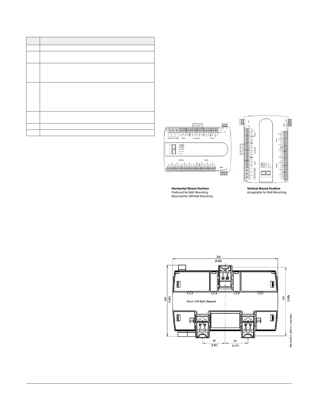
Figure 2: Controller Mounting Positions
Mounting Features and Dimensions
See Figure 3 for mounting dimensions in millimeters
and inches. Inches are listed in parenthesis. Figure
3 also illustrates the DIN rail channel and the
mounting clips in an extended position.
Figure 3: Back of Controller
FAC3613 Advanced Application Field Equipment Controller Installation Guide 3