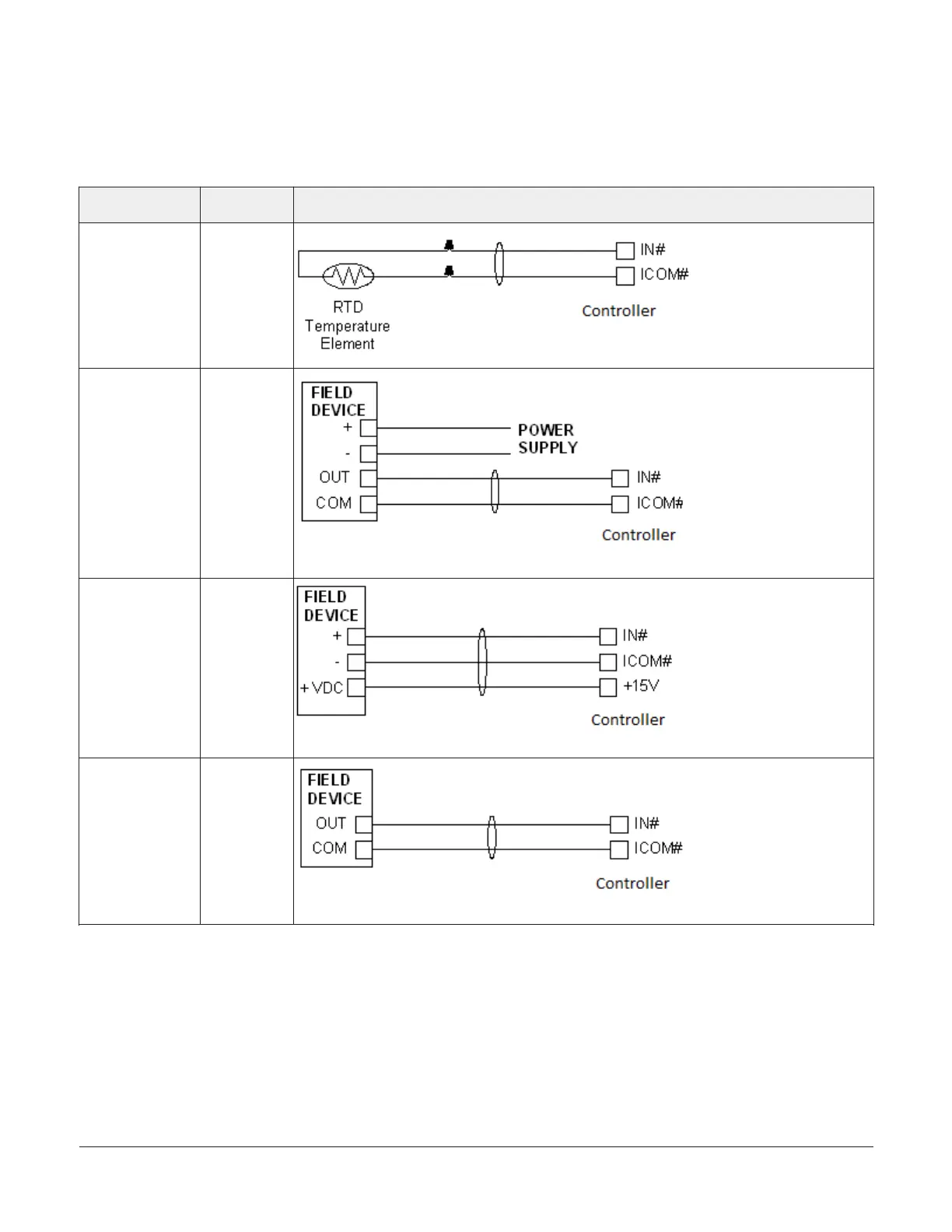
Termination diagrams
A set of Johnson Controls termination diagrams
provides details for wiring inputs and outputs to the
controllers. See the figures in this section for the
applicable termination diagrams.
Table 5: Termination details
Type of field
device
Type of Input/
Output
Termination diagrams
Temperature
Sensor
UI
Voltage Input -
External Source
UI
Voltage Input -
Internal Source
UI
Voltage Input
(Self-Powered)
UI
FAC3613 Advanced Application Field Equipment Controller Installation Guide 11