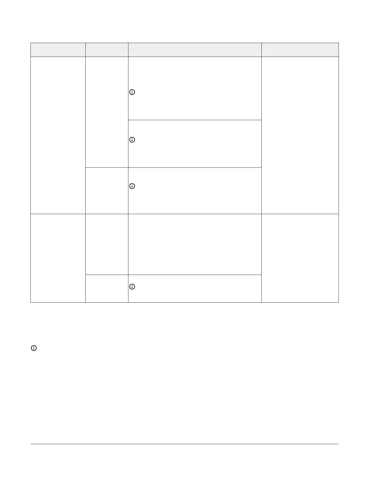
Table 2: Terminal blocks, functions, ratings, requirements, and cables
Terminal block label Terminal label Function, ratings, requirements
Determine wire size and
maximum cable length
Analog Output - Voltage Mode (0–10 VDC)
10 VDC maximum output voltage
10 mA maximum output current
Required an external load of 1,000 ohms or more.
Note: The Analog Output (AO) operates in the
Voltage Mode when connected to devices with
impedances greater than 1,000 ohms. Devices that
drop below 1,000 ohm may not operate as intended
for Voltage Mode applications.
OUTn
Analog Output - Current Mode (4–20 mA)
Requires an external load between 0 and 300 ohms.
Note: The Analog Output (AO) operates in the
Current Mode when connected to devices with
impedances less than 300 ohms. Devices that
exceed below 300 ohms may not operate as
intended for Current Mode applications.
ANALOG
(Outputs)
OCOMn
Analog Output Signal Common for all Analog OUT
terminals.
Note: All Analog Output Common terminals
(OCOMn) share a common, which is isolated from
all other commons. One common screw terminal
point is provided for every two output screw
terminal points.
See Guideline C in Table 3.
OUTn
Binary Output - 24 VAC Triac Class 2, 24 V, 500 mA
(External Power Source)
Connects OUTn to OCOMn when activated.
External Power Source Requirements:
30 VAC maximum output voltage
0.5 A maximum output current
1.3 A at 25% duty cycle
40 mA minimum load current
BINARY
(Output)
OCOMn
Binary Output Common (for OUTn terminal)
Note: Each Binary Output Common terminal
(OCOMn) is isolated from all other commons,
including other Binary Output Common terminals.
See Guideline C in Table 3.
Cable and wire length guidelines
The following table defines cable length guidelines
for the various wire sizes that may be used for
wiring low-voltage (<30 V) input and outputs.
Note: The required wire sizes and lengths
for high-voltage (>30 V) Relay Outputs are
determined by the load connected to the relay,
and local, national, or regional electrical codes.
FAC3613 Advanced Application Field Equipment Controller Installation Guide8