Network Room Module Technical Bulletin 28
B
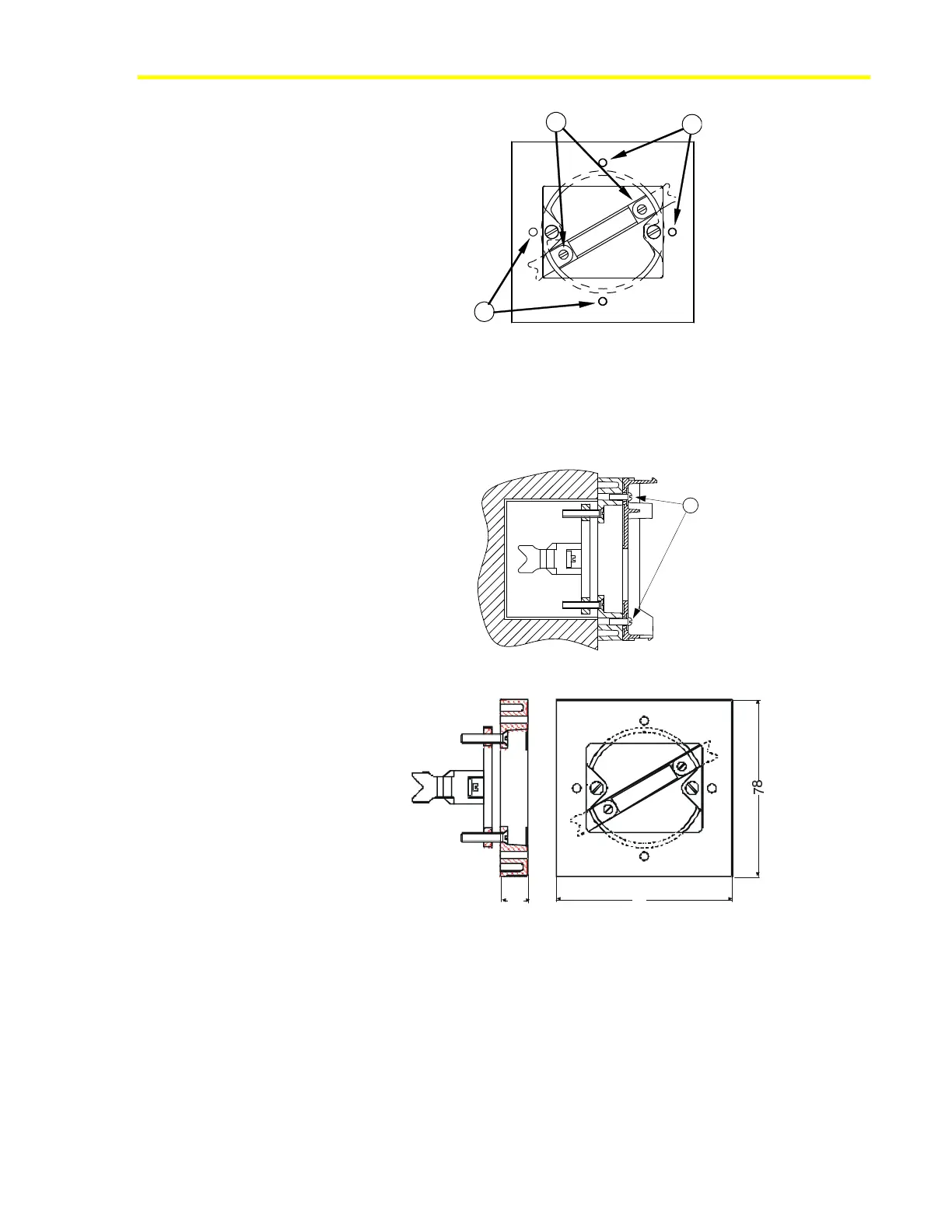
C
C
Figure 23: Front View of Wall Box Mounting Kit
3. Tighten screws (B) until the prongs clamp properly in the wall box.
4. Mount the base of the module on the kit, as shown in Figure 24, using
the two screws included in the kit and inserting them into two opposite
holes of the four holes marked (C).
C
Figure 24: Wall Box Mounting Kit with Module Base
12
78
Wall -Box.cdr
Figure 25: Dimensions (mm) of the Recessed Wall Box Mounting Kit