RWH ROTARY SCREW COMPRESSOR UNITS
OPERATION
070.620-IOM (DEC 12)
Page 17
FULL TIME PUMP SYSTEM
The full time pump system provides all oil ow requirements
for the compressor, including control oil pressure, as well as
lubrication and cooling oil ow. The pump runs continuously.
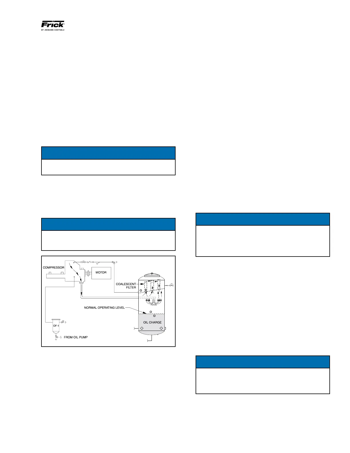
COMPRESSOR OIL SEPARATION SYSTEM
The RWH is an oil ooded screw compressor. Most of the oil
discharged by the compressor separates from the gas ow
in the oil charge reservoir. Some oil, however, is discharged
as a mist which does not separate readily from the gas ow
and is carried past the oil charge reser voir. One or more
coalescer lter elements then COALESCE the oil mist into
droplets which fall to the bottom of the coalescer section of
the oil separator. See Figure 21. The return of this oil to the
compressor is controlled by a throttling valve on both high
stage and booster applications.
NOTICE
Open throttling valve only enough to keep coalescer
end of separator free of oil.
The sight glass located near the bottom of the coales cer sec-
tion of the oil separator should remain empty during normal
operation. If an oil level develops and remains in the sight
glass, a problem in the oil return separation system or com-
pressor operation has developed. Refer to MAINTENANCE
for information on how to correct the prob lem.
NOTICE
The normal operating level is midway between the two
sight glasses located midway along the oil separator
shell.
Figure 21 - Oil Separation System
DISCHARGE BUTTERFLY CONTROL OIL SYSTEM
The valve can open when Compressor Start Output is
energized and immediately closes when the output is de
energized.
The Discharge Buttery Valve Solenoid output will only be
energized when the Discharge Pressure reaches the Con
densing Pressure. If the Solenoid needs to open when the
compressor starts, it can be controlled from the Compressor
Run Output.
The valve is controlled to maintain a minimum differential
pressure that will provide oil ow and keep the oil pressure
above the oil safeties. The Compressor Differential Pressure
Setpoint can be used to set a higher differential pressure
setting when necessary.
If the Lock Open Flag is set to True, after the valve opens
to 100% it will remain in this position until the compressor
is turned off. If the Lock Open Flag is set to False, the valve
will continue to modulate based on the compressor differ
ential pressure.
COMPRESSOR HYDRAULIC SYSTEM
The compressor hydraulic system moves the movable slide
valve (MSV) to load and unload the compressor. It also moves
the movable slide stop (MSS) to increase or decrease the
compressor’s volume ratio (Vi).
The hydraulic cylinder located at the inlet end of the SGC
compressor serves a dual purpose. It is separated by a xed
bulkhead into two sections. The movable slide valve (MSV)
sec tion is to the left of the bulkhead and the movable slide
stop (MSS) to the right. Both sections are considered double
acting hydraulic cylinders as oil pressure moves the pistons
in either direction.
Both sections are controlled by doubleacting, fourway
solenoid valves which are actuated when a signal from the
appropriate micropro cessor output energizes the solenoid
valve. Valves SV2, SV3, SC1, SC3, and T1 are always open.
NOTICE
The solenoid coils can be serviced or replaced without
evacuating the package. However, if the hydraulic so-
lenoid valves or manifold block needs to be serviced
or replaced, then the compressor package must be
evacuated.
SINGLE-ACTING MODE - High Stage
Close valve at SC2
Open valve at BP (bypass)
High stage compressor loading: The compressor loads when
MSV solenoid YY2 is energized and oil ows from the unload
side of the cylinder out port SC1, through valve ports A and
T to compressor suction. Simultaneously, discharge pressure
loads the slide valve.
High stage compressor unloading: The compressor unloads
when MSV solenoid YY1 is energized and oil ows from the
oil manifold through valve ports P and A to cylinder port SC1
and enters the unload side of the cylinder. Simultaneously,
gas on the load side of the cylinder is vented through port
SC2 and valve BP to compressor suction.
NOTICE
To control the rate of loading and unloading, change
cycle time, proportional band, and dead band setpoints
with Quantum control. If additional control is needed,
throttle SC2 or BP.
DOUBLE-ACTING MODE - Booster
Open valve at SC2
Close valve at BP (bypass)