RWH ROTARY SCREW COMPRESSOR UNITS
INSTALLATION
070.620-IOM (DEC 12)
Page 5
Installation
FOUNDATION
If RWH Rotary Screw Compressor Unit is shipped mounted
on a wood skid, it must be removed prior to unit installation.
WARNING
Allow space for servicing the unit per factory drawings.
The rst requirement of the compressor foundation is that
it must be able to support the weight of the compressor
package including coolers, oil, and refrigerant charge. Screw
compressors are capable of converting large quantities of
shaft power into gas compression in a relatively small space
and a mass is required to effectively dampen these relatively
highfrequency vibrations.
Firmly anchoring the compressor package to a suitable
foundation by proper application of grout and elimination of
piping stress imposed on the compressor is the best insur
ance for a troublefree installation. Use only the certied
general arrangement drawings from Frick to determine the
mounting locations and to allow for recommended clear
ances around the unit for ease of operation and servicing.
Foundations must be in compliance with local building codes
and materials should be of industrial quality.
Anchor bolts are required to rmly tie the unit to the foun
dation. Once the unit is rigged into place (See RIGGING and
HANDLING), the package must be level and raised at least
one inch for grouting. An expansiontype epoxy grout must
be worked under all areas of the base with no voids. The
base should be lled concrete and smoothed to allow water
runoff. Finish with a nonslip coating.
When installing on the upper oors of buildings, extra precau
tions should be taken to prevent normal package vibration
from being transferred to the building structure. It may be
necessary to use rubber or spring isolators, or a combination
of both, to prevent the transmission of compressor vibration
directly to the structure. However, this may increase package
vibration levels because the compressor is not in contact with
any damping mass. The mounting and support of suction
and discharge lines is also very important. Rubber or spring
pipe supports may be required to avoid exciting the build
ing structure at any pipe supports close to the compressor
package. It is best to employ a vibration expert in the design
of a proper mounting arrangement.
In any screw compressor installation, suction and discharge
lines should be supported in pipe hangers (preferably within 2
ft. of vertical pipe run) so that the lines won’t move if discon
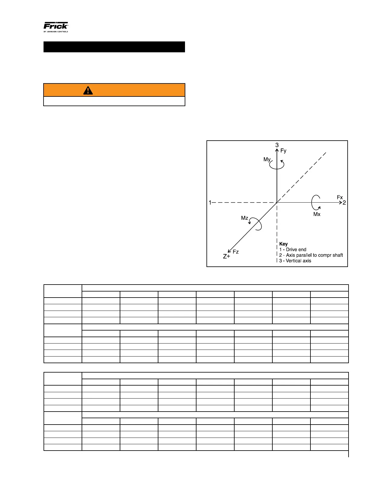
nected from the compressor. See tables for Allowable Forces.
Table C.1 - Alowable Forces
Nozzle Nominal Size DN *
Force Nm 100 150 200 250 300 350 400
F
x
1,368 2,094 2,815 3,328 3,960 4,908 5,772
F
y
3,434 5,253 7,052 8,349 9,938 12,294 14,455
F
z
2,336 3,383 4,527 5,178 5,992 6,662 7,492
F
r
4,373 6,590 8,841 10,373 12,261 14,819 17,274
Nozzle Nominal Size NPS *
Force lbf 4 6 8 10 12 14 16
F
x
308 471 633 748 890 1,103 1,297
F
y
772 1,181 1,585 1,877 2,234 2,764 3,250
F
z
525 761 1,018 1,164 1,347 1,496 1,684
F
r
983 1,482 1,987 2,332 2,756 3,331 3,883
Table C.2 - Alowable Forces
Nozzle Nominal Size DN *
Force Nm 100 150 200 250 300 350 400
M
x
2,069 2,754 3,672 4,212 5,097 6,232 7,316
M
y
1,253 2,126 2,836 3,648 4,190 5,656 6,781
M
z
1,253 1,698 2,264 2,814 3,334 4,491 5,450
M
r
2,724 3,871 5,163 6,242 7,393 9,539 11,367
Nozzle Nominal Size NPS *
Force lbf 4 6 8 10 12 14 16
M
x
1,526 2,031 2,709 3,107 3,759 4,597 5,396
M
y
924 1,568 2,091 2,691 3,090 4,171 5,001
M
z
924 1,252 1,670 2,076 2,459 3,312 4,020
M
r
2,009 2,855 3,808 4,604 5,453 7,036 8,384
* Nozzle nominal size DN is expressed in millimeters; nozzle nominal size NPS is expressed in inches.
Figure 1 - Denition of Axes