RWH ROTARY SCREW COMPRESSOR UNITS
MAINTENANCE
070.620-IOM (DEC 12)
Page 30
RECOMMENDED MAINTENANCE PROGRAM
In order to obtain maximum compressor unit perform ance
and ensure reliable operation, a regular main tenance program
should be followed.
The compressor unit should be checked daily for leaks, ab
normal vibration, noise, and proper operation. A log should
also be maintained. Initial Oil analysis and Vibration analysis
should be done at startup and continued as recommended
by the Maintenance Schedule
.
VIBRATION ANALYSIS
Periodic vibration analysis can be useful in detecting bearing
wear and other mechanical failures. If vibration analysis is
used as a part of your preventive main tenance program, take
the following guidelines into consideration.
1. Always take vibration readings from exactly the same
places and at exactly the same percentage of load.
2. Use vibration readings taken from the new unit at startup
as the base line reference.
3. Evaluate vibration readings carefully as the instru ment
range and function used can vary. Findings can be easily
misinterpreted.
MAINTENANCE SCHEDULE
This schedule should be followed to ensure troublefree operation of the compressor unit.
PREVENTATIVE MAINTENANCE
Performing a few preventative maintenance procedures will
extend the life of your pump and reduce the cost per gallon
pumped.
1. Lubrication Grease all zerks after every 500 hours of
operation or after 60 days, whichever occurs rst. If service
is severe, grease more often. Do it gently with a hand gun.
Use #2 ball bearing grease for normal applications. For hot
or cold applications, use appropriate grease.
2. Packing Adjustment Occasional packing adjustment
may be required to keep leakage to a slight weep; if impos
sible to reduce leakage by gentle tightening, replace pack
ing or use different type. See Technical Service Manual on
particular model series for details on repacking.
3. End Clearance Adjustment After long service the run
ning clearance between the end of the rotor teeth and the
head may have increased through wear to the point where
the pump is losing capacity or pressure. Resetting end clear
ance will normally improve pump performance. See Technical
Service Manual on particular model series for procedure on
adjusting end clear ance for the pump involved.
a. Check bolts, shim packs, center inserts, keys, and all bolt torques.
b. Check and torque all terminals in the processor and starter panel per the specication posted in the enclosure.
c. Check calibration of Slide Valve, Slide Stop, pressures and temperatures. Calibration should be conducted with NIST certied devices.
d. Verify tightness of bolts on suction and discharge anges. See table below for torque requirements.
e. Vibration measurement must be carried out continuously to obtain optimum preventative control on bearings. If not continuously
controlled, then every 6 months, more frequently if levels increase.
f. Units with varible speed drives check for excess vibration and skip frequencies anytime unit operating conditions change.
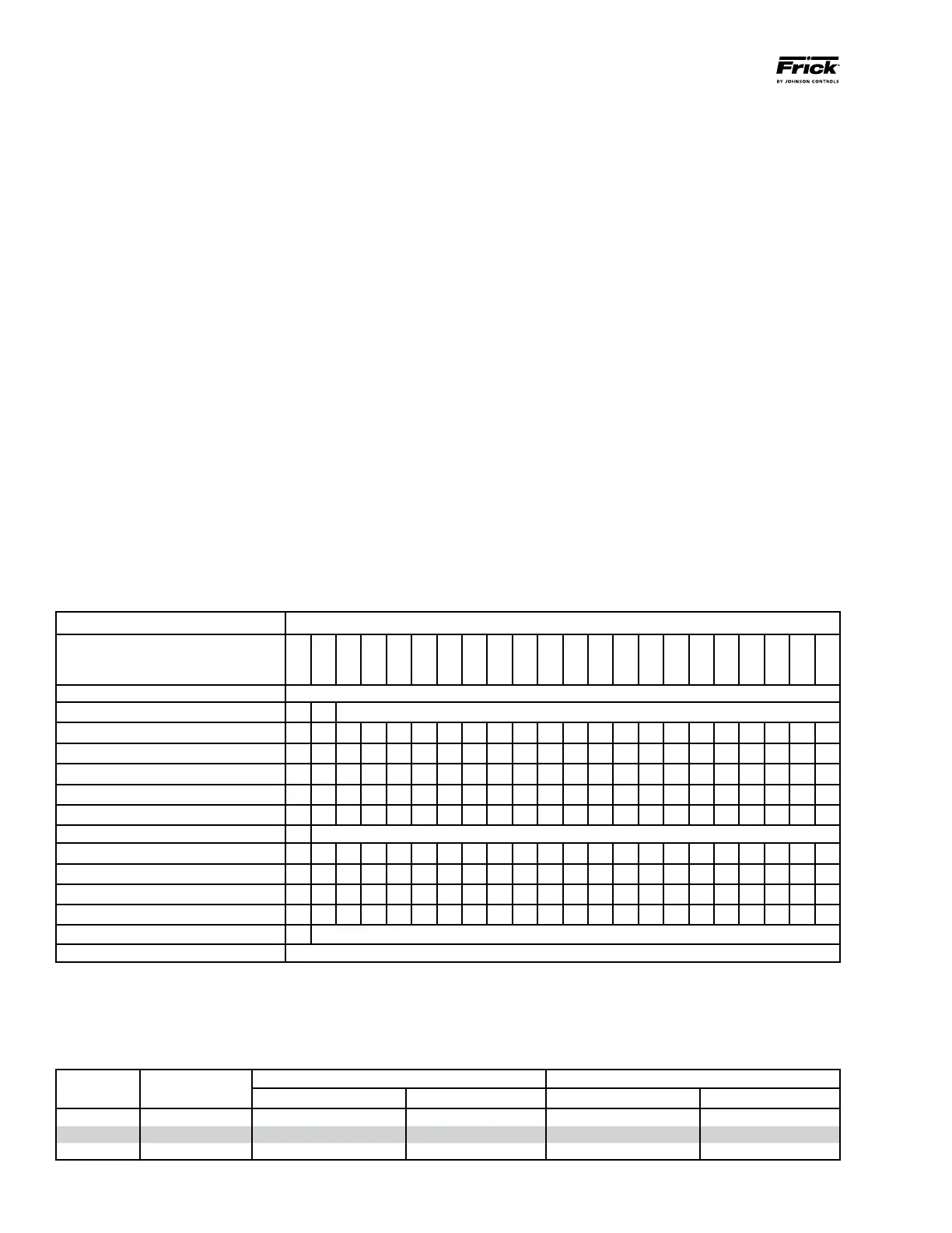
FREQUENCY OR HOURS OF OPERATION (MAXIMUM)
MAINTENANCE
200
1000
5000
8000
10,000
15,000
20,000
25,000
30,000
35,000
40,000
45,000
50,000
55,000
60,000
65,000
70,000
75,000
80,000
85,000
90,000
95,000
Change Oil As Directed By Oil Analysis
Oil Analysis
n
Every 6 Months
Replace Filters
n
n
n
n
n
n
n
n
n
n
n
Clean Oil Strainers
n
n
n
n
n
n
n
n
n
n
n
Clean Liquid Strainers
n
n
n
n
n
n
n
n
n
n
n
Replace Coalescers
n
n
n
Check and Clean Suction Strainer
n
n
n
n
n
n
n
n
n
n
n
Check Coupling (a)
n
Annually Regardless of Operating Hours
Suction & Disch Flange Bolts (d)
n n n n n n n n n n n n n n n n n n n n n n
VFD Units Check Skip Freq. (f)
n n n n n n n n n n n n n n n n n n n n n n
Check Electrical Connections (b)
n n n n n n n n n n n n n n n n n n n n
Check Sensor Calibration (c)
n n n n n n n n n n n n n n n n n n n n n
Vibration Analysis (e)
n
Every 6 Months, More Frequently If Levels Increase
Replace Shaft Seal When Leak Rate Exceeds 7 8 Drops Per Minute
RWH
MODEL
Compressor
Model
Discharge Flange to Separator Flange Suction Flange
Bolt Size Torque* (ft-lb) Bolt Size (in.) Torque* (ft-lb)
852 TDSH 408S M24 X 3.0 240 M30 X 3.5 350
1179 TDSH 408L M24 X 3.0 240 M30 X 3.5 350
1395 TDSH 408XL M24 X 3.0 240 M30 X 3.5 350
* Based on: GasketsGarlock
®
BlueGard
®
3300; Boltsclass 8.8 or stronger hex head bolts, lightly oiled and clean