RWH ROTARY SCREW COMPRESSOR UNITS
INSTALLATION
070.620-IOM (DEC 12)
Page 6
The resultant force, Fr, is given by Equation (C1):
where F
x
, F
y
, and F
z
are the force components along the x,
y, and the zaxis, respectively
The resultant moment Mr, is given by Equation (C.2):
where M
x
, M
y
, and M
z
are the force components along the
x, y, and the zaxis, respectively
Consult a licensed architect to determine the proper foun
dation requirements for any large engine or turbine drive.
When applying screw compressors at high pressures, the
customer must be prepared for package vibration and noise
higher than the values predicted for normal refrigeration duty.
Proper foundations and proper installation methods are vital;
and even then, sound attenuation or noise curtains may be
required to reduce noise to desired levels.
For more detailed information on Screw Compressor
Foundations, please request Frick
®
publication 070.210-IB.
RIGGING and HANDLING
WARNING
This screw compressor package may be top-heavy. Use
caution in rigging and handling.
The unit can be moved with rigging, using a crane and
spreader bars, by hooking into all lifting eyes on the package.
Ap propriate adjustment in the lifting point should be made to
compensate for the center of gravity. Refer to supplied engi
neering drawings to determine the package center of gravity.
CHECKING MOTOR/COMPRESS OR ROTA TION
WARNING
Make sure coupling hubs are tight-ened to the shaft
before rotatingthe motor to prevent them from ying
off and possibly causing serious injury or death.
WARNING
Injury may occur if loose clothing, etc, becomes en-
tangled on the spinning motor shaft.
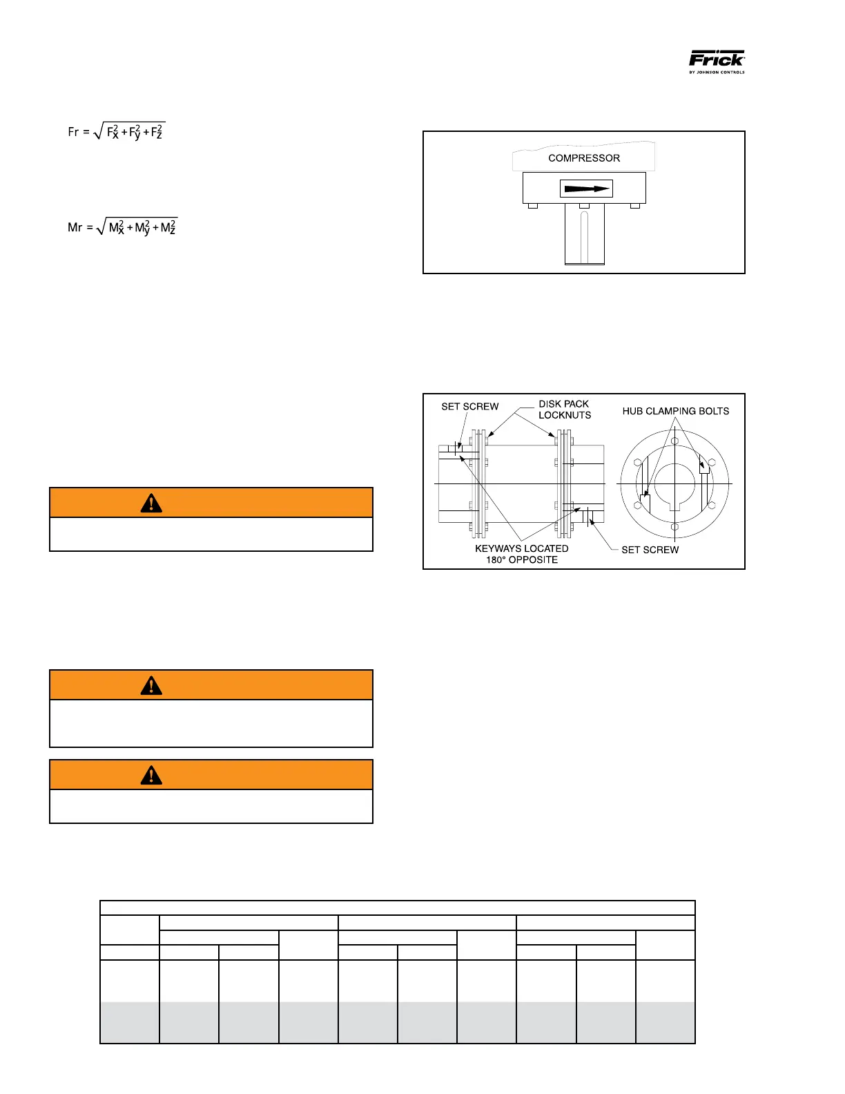
COMPRESSOR ROTATION IS CLOCKWISE WHEN FACING
THE END OF THE COMPRESSOR SHAFT. Under NO condi
tions should the motor rotation be check ed with the coupling
center installed as damage to the com pressor may result.
BP SERIES COUPLING DATA TABLE
BP
DISC PACK LOCKNUT HUB CLAMPING BOLTS KEYWAY SETSCREW
SERIES
TORQUE (Lube*)
SIZE UNF
TORQUE
SIZE UNF
TORQUE
SIZE NC
SIZE FT-LB NM FT-LB NM FT-LB NM
BP 38 17 23.1 5/16-24 41 55.6 3/8-24 22 29.8 3/8-16
BP 43 40 54.2 7/16-20 41 55.6 3/8-24 22 29.8 3/8-16
BP 48 40 54.2 7/16-20 41 55.6 3/8-24 53 71.9 1/2-13
BP 53 60 81.4 1/2-20 66 89.5 7/16-20 53 71.9 1/2-13
BP 58 120 162.7 5/8-18 101 137.0 1/2-20 53 71.9 1/2-13
BP 63 120 162.7 5/8-18 101 137.0 1/2-20 186 252.2 3/4-10
Bump the motor to check for correct compressor rotation.
After verication, install disc drive spacer, as applicable.
COMPRESSOR/MOTOR COUPLING INSTALLATION
The job coupling may be one of those described below or
it may be custom specied for the application. If the latter,
refer to the engineering prints and documents as well as
coupling manufacturer instructions as applicable, based on
the actual coupling supplied.
Figure 2 - BP Coupling
BP COUPLING INSTALLATION PROCEDURE
1. Install the motor and compressor coupling hubs and keys
on their respective shafts. Ensure that they can slide hori
zontally so that once the disc packs are installed, no axial
stress is transferred to the disc packs by a stuck coupling
hub. Use no lubricants.
2. Rotate both hubs so that the keys are 180° opposed (See
Figure 2). With the hubs mounted and the axial spacing set,
proceed to place the spacer between the two hub anges.
Care should be taken when handling the spacer. Be sure the
spacer is fully supported at this time. Damage to the unit
ized ex discs may result after they have been installed if
the spacer is not fully supported.
Install the unitized ex disc at this time. Start a bolt through
a bolt hole in the spacer. Put the unitized ex disc between
the hub and spacer until a bushing hole in the unitized ex
disc lines up with the bolt. Slide the bolt through the bushing
hole in the unitized ex disc. Install the locknut until it is snug.
Make sure that all bolt threads are clean and lightly oiled. Do