RWH ROTARY SCREW COMPRESSOR UNITS
OPERATION
070.620-IOM (DEC 12)
Page 21
• Using the chart below, as long as the control input
is 155°F the output will be at 20% with proportional
control only. Integral control will increase the output
in increments, over time, to correct the control input
to the setpoint.
Control Input Output %
150°F 0%
155°F 20%
160°F 40%
165°F 60%
170°F 80%
175°F 100%
Based on these descriptions set PID #1 for EZ-Cool
™
LIOC
per Figure 25 as a starting point. Tuning of the output will be
required. There should be no need to use a derivative gain.
SUCTION CHECK VALVE BYPASS
The RWH unit is equipped with a lowpressuredrop suction
check in the suction piping. Units that have an 8" or larger
stop angle or globe valve should be piped as shown in the
shaded area of Figure 25. During normal operation, valve
NV1 is closed. This is a pumpout connection to allow re
frigerant removal to the system suction prior to evacuation
for servicing. Valve NV2 must be open in most systems
at all times. It should normally be cracked open to allow
the oil separator to slowly bleed down to approximately
system suction pressure when the unit is stopped (having
this valve cracked open allows the compressor drive mo
tor to have an easier start, and the discharge check valve
will seat more tightly). If the drive coupling backspins, start
closing the valve until the backspin stops. If the separator oil
level foams excessively on shutdown, NV2 should be closed
slightly. If the separator takes more than 20 – 30 minutes to
equalize to suction pressure after shutdown, NV2 can be
opened slightly. See Figure 26.
Check valve CV is installed on all RWH packages. On high
stage systems, check valve CV is installed with a 45 psi
spring to avoid the possibility of backfeeding to a shutdown
compressor from a common economizer vessel.
On booster systems, check valve CV is installed with a 25 psi
spring to avoid the possibility of air ingress into the system,
if the system suction pressure is below atmospheric.
Figure 26 - Suction Check Valve Bypass
LOW AMBIENT OPERATION
It is recommended that oil separators be insulated as a
minimum requirement to preserve the heat generated by
the oil heaters. It is important that the coalescer end of the
separator be insulated to prevent refrigerant condensation.
On systems located outdoors or in unheated buildings where
the ambient temperature could drop below +40°F, insulating
and/or heat tracing of the compressor lube oil systems is
highly recommended.
When low ambient temperatures (below +20°F) are a pos
sibility, it is recommended that lube oil lines, oil lters, oil
pumps, and oil coolers be heat traced and insulated.
Freezeup protection must also be provided for all water
cooled equipment
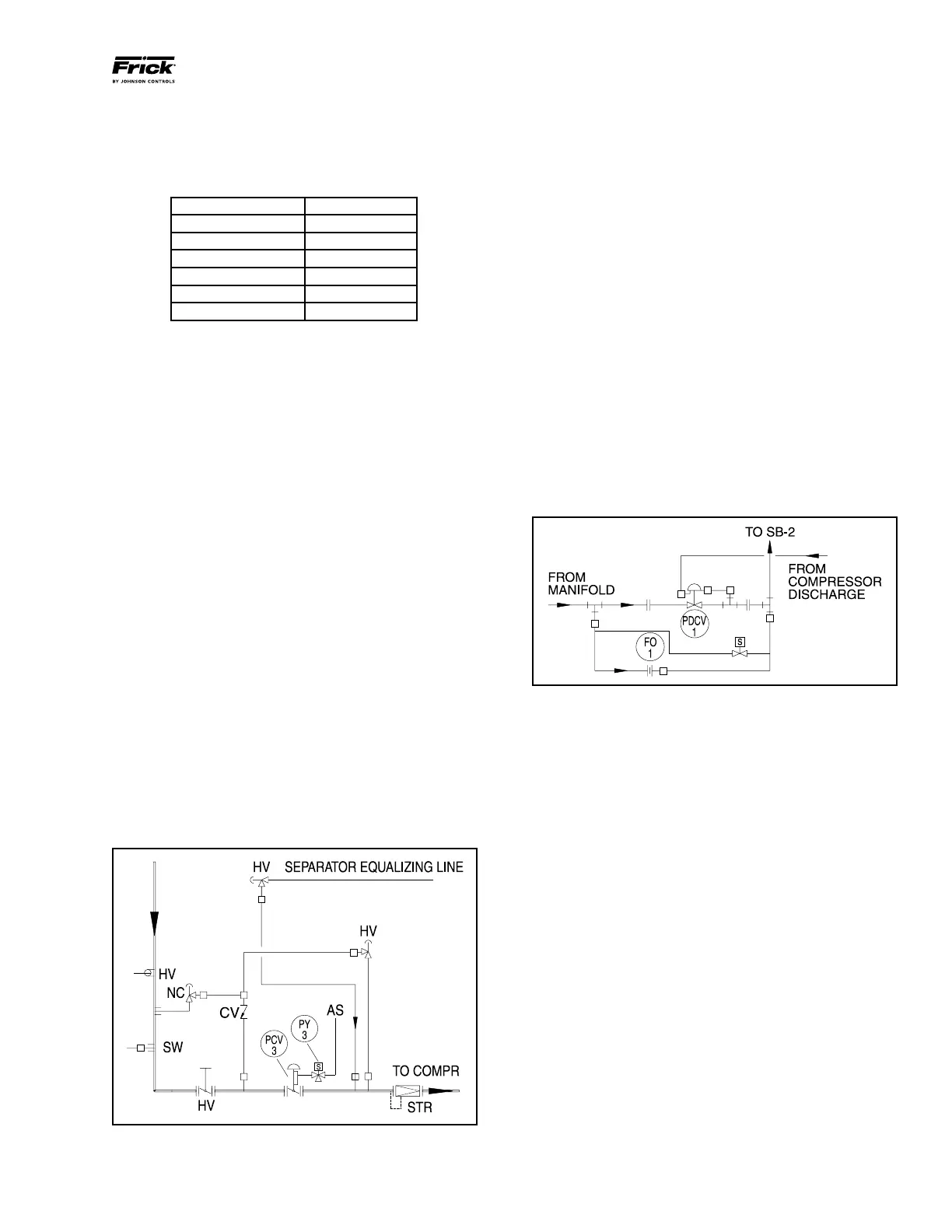
BALANCE PISTON PRESSURE REGULATOR
A Balance Piston Pressure Regulator may be required to
reduce the extended overbalance from the thrust balance
piston at part load.
High-Stage SB-2 Oil Supply Line Diagram, Figure 27, shows
the three additions described below arranged in parallel.
Figure 27 - High-Stage SB-2 Oil Supply Line Diagram
PRESSURE-REGULATING VALVE: Discharge pressure deter
mines compressor thrust balance. The proper setting for the
pressureregulating valve is 50 psi (±15) below DISCHARGE
pressure when slide valve is less than 65%.
SOLENOID VALVE: Energizing, or opening, the solenoid valve
pressurizes the balance piston with full oil pressure from the
oil manifold, bypassing the A4ALE Pressure Regulating Valve.
Deenergizing, or closing, the solenoid valve pressurizes
the balance piston with oil pressure regulated by the A4ALE
Pressure Regulating Valve. The solenoid valve is not always
required. Refer to project prints and documents.
Signals from the control panel operate the solenoid valve
(output module 12 on micro panel). The solenoid valve should
open when the slide valve position is 70% or greater, and
close when the slide valve position is 65% or less. These
setpoints may vary from project to project. Refer to project
documentation.
ORIFICE: The orice ensures oil supply to the inlet end bear
ings during upset conditions such as startup.
INITIAL START-UP
Initial start-up must be performed under the super vision
of a Johnson Controls-Frick authorized start-up represen-
tative to prevent voiding the compressor warranty. Prior
to the start-up, the prestart check must be accomplish ed.
See Prestart Checklist in the Forms section of this manual.