RWH ROTARY SCREW COMPRESSOR UNITS
MAINTENANCE
070.620-IOM (DEC 12)
Page 26
WARNING
Oil-entrained refrigerant may vaporize, causing a sepa-
rator pressure increase. Repeat venting and recovery
procedure, if necessary.
5. Open the drain valve(s) located on the underside of the
separator and drain the oil.
6. Drain the oil lter(s) OF1 and, if ap plicable, the oil coolers
and lter OF2.
7. Remove the old lter cartridges, then install new ones
(as previously described in the section OIL FILTER (OF-1)
MAIN SINGLE/DUAL).
8. Remove, clean, and reinstall strainer elements in the
strainers.
9. Evacuate unit to 29.88" Hg (1000 microns) vacuum.
10. Open the suction service valve and pressurize the unit
to system suction pressure. Close the suction valve and leak
test.
11. Add oil by attaching a suitable pressuretype hose to the
oil drain valve located under the separator. Using a pressure
type oil pump and recommended Frick
®
oil, open the drain
valve and ll the separator until the oil level is midway in the
top sight glass.
NOTICE
Evacuation of the oil separator will assist the ow of
oil into the unit. Also, ll slowly because oil will ll up
in the separator faster than it shows in the sight glass.
Refer to the table in the OIL CHARGE section for approximate
oil charge quantities.
12. Open the suction and discharge service valves, and also
the liquid injection and economizer service valves, if ap
plicable.
13. Close the disconnect switch for the compressor motor
starter.
14. Start the unit.
PUMP DISASSEMBLY
DANGER
BEFORE OPENING ANY VIKING PUMP LIQUID CHAM-
BER (PUMPING CHAMBER, RESERVOIR, JACKET, ETC.)
ENSURE:
1. That any pressure in the chamber has been completely
vented through suction or discharge lines or other ap-
propriate openings or connections.
2. That the driving means (motor, turbine, engine, etc.)
Has been “locked out” or made non operational so that it
cannot be started while work is being done on the pump.
FAILURE TO FOLLOW ABOVE LISTED PRECAUTIONARY
MEASURES MAY RESULT IN SERIOUS INJURY OR DEATH.
1. Mark head and casing before disassembly to ensure
proper reassembly. The idler pin, which is offset in the pump
head, must be positioned up and equal distance between
port connections to allow for proper ow of liquid through
the pump.
2. Remove the head capscrews.
3. Tilt top of head back when removing to prevent idler from
falling off idler pin.
4. Remove idler and bushing assembly. If idler bushing
needs replacing, see INSTALLATION OF CARBON GRAPHITE
BUSHINGS.
5. Insert a brass bar or piece of hardwood in the port open
ing and between rotor teeth to keep shaft from turning.
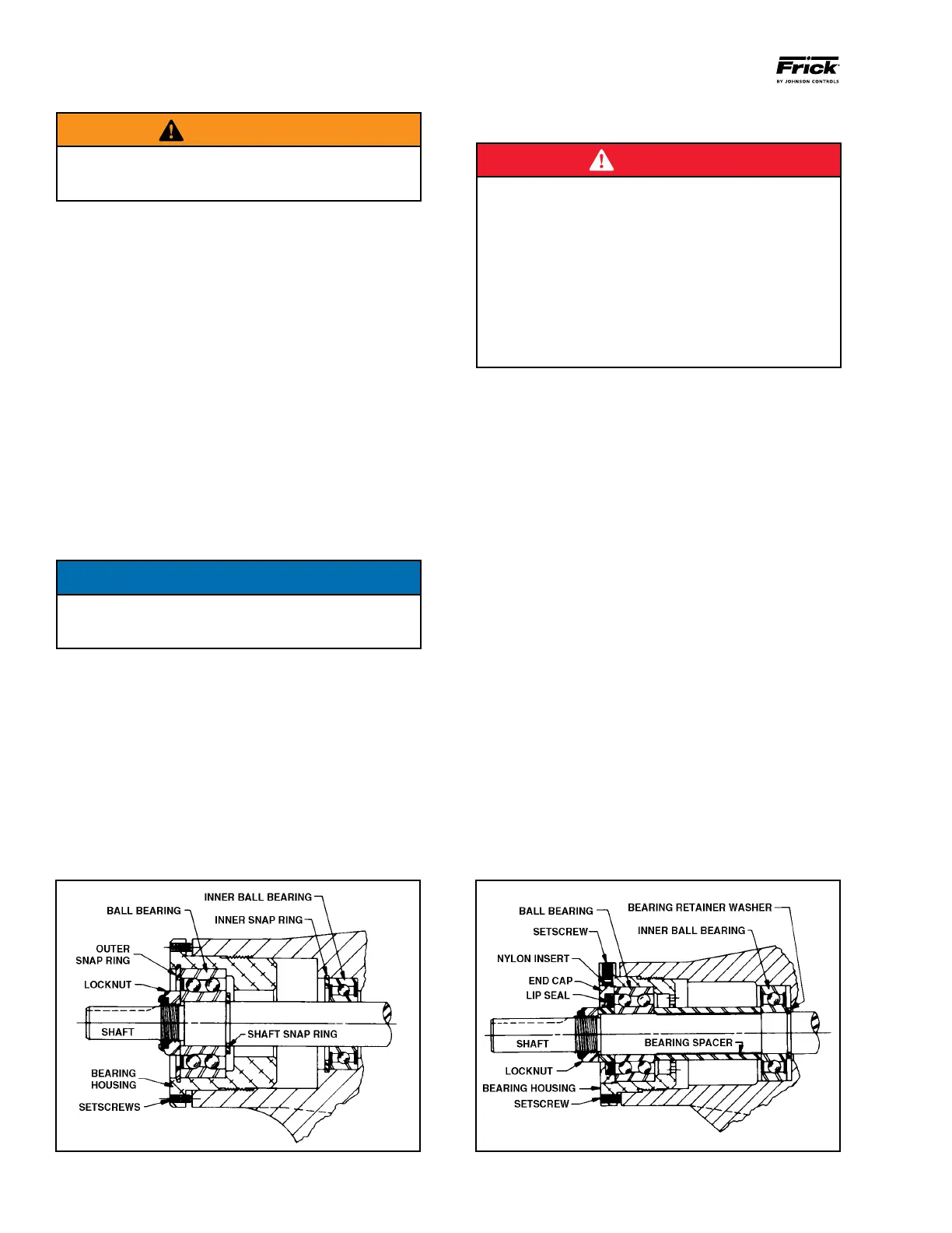
Turn the locknut counterclockwise and remove locknut. See
Figure 28 or 29.
6. Loosen two setscrews in face of bearing housing and turn
thrust bearing assembly counterclockwise and remove from
casing. See Figure 28 or 29.
7. GG, HJ, HL: Remove snap ring from shaft. See Figure 28.
AS, AK, AL: Remove bearing spacer from shaft. See Figure
29.
8. Remove brass bar or piece of hardwood from port opening.
9. The rotor and shaft can now be removed by tapping on
end of shaft with a lead hammer or, if using a regular ham
mer, use a piece of hardwood between shaft and hammer.
Figure 28 - Thrust-Bearing assembly (GG, HJ, HL) Figure 29 - Thrust-Bearing assembly (AS, AK, AL)