RWH ROTARY SCREW COMPRESSOR UNITS
MAINTENANCE
070.620-IOM (DEC 12)
Page 33
10. The voltage reading should be between 1.1 VDC and 1.29
VDC at standard atmospheric pressure (see Step 12).
11. Since the discharge pressure, PE3, cannot be closed off
from its sensing point (code require ments), close all trans
ducers from atmosphere and open them to their sensing
points so all transducers can equalize to separator pressure.
12. Measure the voltage of PE3 on connector P5B (terminals
WHT and BLK) on the Analog Board.
13. Measure the voltage of PE1 on connector P5A (terminals
WHT and BLK) on the Analog Board.
14. These two voltages should be within .04 VDC of one
another.
15. Test is complete.
Make a list of all deviations from normal plant operation and
normal compressor unit operation. Delete any items which
do not relate to the symptom and separately list those items
that might relate to the symptom. Use the list as a guide to
further investi gate the problem.
The second step in problem solving is to decide which items
on the list are possible causes and which items are additional
symptoms. High discharge temperature and high oil tem
perature readings on a display may both be symptoms of a
problem and not casually relat ed. High suction superheat or
a low receiver level, however, could cause both symptoms.
The third step is to identify the most likely cause and take
action to correct the problem. If the symptoms are not
relieved move to the next item on the list and repeat the
procedure until you have identied the cause of the problem.
Once the cause has been identi ed and con rmed make the
necessary correc tions.
PRESSURE TRANSDUCERS - TESTING
1. Shut down the compressor and allow pressures to equalize.
2. Isolate suction transducer PE4 from the unit and depres
surize. Ensure that the transducer has proper voltage for
excitation. Measure across the red and black wires (power
and DC common) of the transducer. Voltage should be 11.8
to 15 VDC.
NOTICE
Recover or transfer all refrigerant vapor, in accordance
with local ordinances, before opening to atmosphere.
3. Measure the voltage of PE4 on connector P6A (terminals
WHT and BLK) on the Analog Board with a digital voltmeter.
4. The voltage reading should be 1.48 VDC to 1.72 VDC at
standard atmospheric pressure (14.7 PSIA or 0 PSIG). When
checking transducers at higher elevations, an allowance in
the readings must be made by subtracting approximately 0.02
VDC per 1000 feet of elevation above sea level. Therefore,
if PE4 is measured at 5000 feet elevation under relatively
normal weather conditions, the output voltage should differ
by 0.10 VDC to read between 1.38 VDC and 1.62 VDC.
5. Isolate the oil pressure transducer PE1 from the package
and open it to atmosphere.
6. Measure the voltage of PE1 on connector P5A (terminals
WHT and BLK) on the Analog Board.
7. The voltage reading should be between 1.1 VDC and 1.29
VDC at standard atmospheric pressure. PE1, PE2, and PE3
all have a span of 500 PSI as compared to PE4 with a span
of 200 PSI. Therefore, atmospheric pressure changes have a
lesser effect which is 0.0067 VDC per 1000 feet of elevation
and 0.00067 VDC per 0.1 inch Hg barometric deviation.
8. Isolate transducer PE2 from the package and depres
surize.
NOTICE
Recover or transfer all refrigerant vapor, in accordance
with local ordinances, before opening to atmosphere.
9. Measure the voltage of PE2 on connector P5B (terminals
WHT and BLK) on the Analog Board.
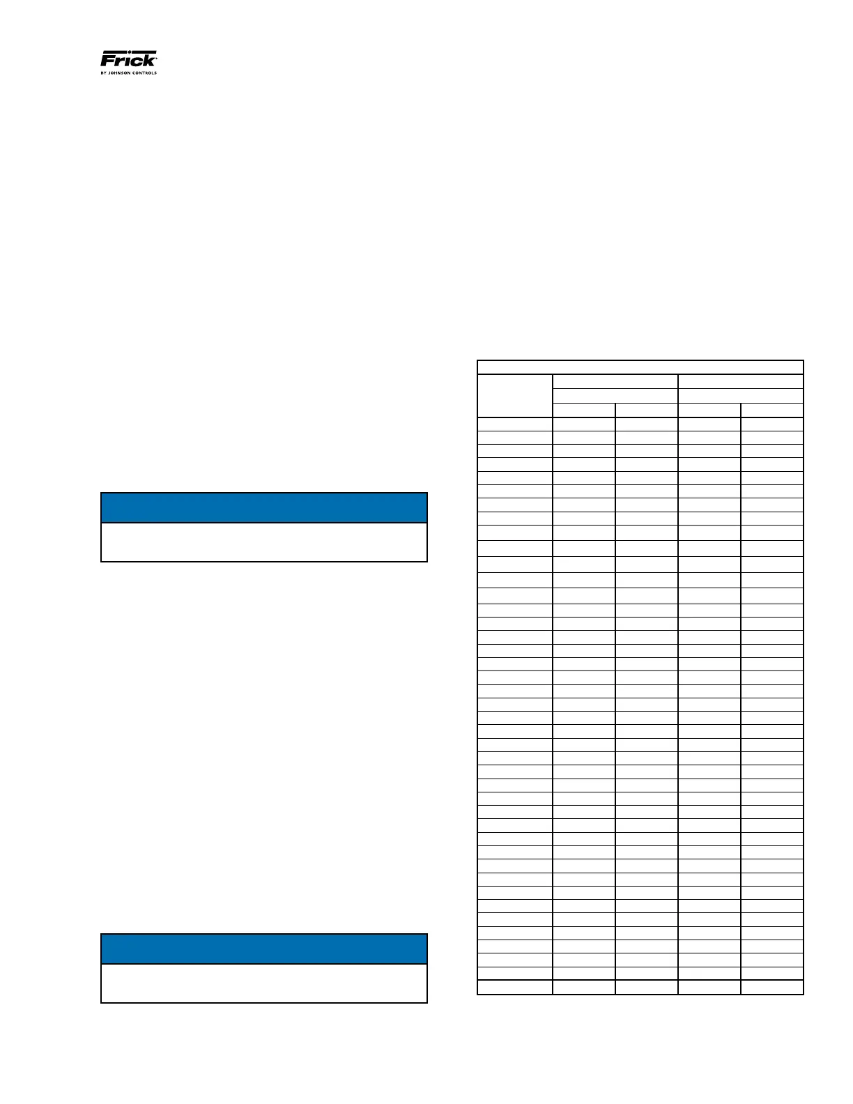
PRESSURE TRANSDUCER CONVERSION DATA
200 psi 500 psi
Sensor Range - PSIG* Range - PSIG*
Voltage low high low high
1.0 29.92" 9.57" 29.92" 4.1
1.1 29.92" 0.3 29.92" 16.6
1.2 29.92" 5.3 17.10" 29.1
1.3 19.74" 10.3 4.1 41.6
1.4 9.57" 15.3 16.6 54.1
1.5 0.3 20.3 29.1 66.6
1.6 5.3 25.3 41.6 79.1
1.7 10.3 30.3 54.1 91.6
1.8 15.3 35.3 66.6 104.1
1.9 20.3 40.3 79.1 116.6
2.0 25.3 45.3 91.6 129.1
2.1 30.3 50.3 104.1 141.6
2.2 35.3 55.3 116.6 154.1
2.3 40.3 60.3 129.1 166.6
2.4 45.3 65.3 141.6 179.1
2.5 50.3 70.3 154.1 191.6
2.6 55.3 75.3 166.6 204.1
2.7 60.3 80.3 179.1 216.6
2.8 65.3 85.3 191.6 229.1
2.9 70.3 90.3 204.1 241.6
3.0 75.3 95.3 216.6 254.1
3.1 80.3 100.3 229.1 266.6
3.2 85.3 105.3 241.6 279.1
3.3 90.3 110.3 254.1 291.6
3.4 95.3 115.3 266.6 304.1
3.5 100.3 120.3 279.1 316.6
3.6 105.3 125.3 291.6 329.1
3.7 110.3 130.3 304.1 341.6
3.8 115.3 135.3 316.6 354.1
3.9 120.3 140.3 329.1 366.6
4.0 125.3 145.3 341.6 379.1
4.1 130.3 150.3 354.1 391.6
4.2 135.3 155.3 366.6 404.1
4.3 140.3 160.3 379.1 416.6
4.4 145.3 165.3 391.6 429.1
4.5 150.3 170.3 404.1 441.6
4.6 155.3 175.3 416.6 454.1
4.7 160.3 180.3 429.1 466.6
4.8 165.3 185.3 441.6 479.1
4.9 170.3 190.3 454.1 491.6
5.0 175.3 195.3 466.6 504.1
At 0 psig 1.094 V 1.494 V 0.968 V 1.268 V
* Below 0 PSIG measured in inches of mercury.