RWH ROTARY SCREW COMPRESSOR UNITS
OPERATION
070.620-IOM (DEC 12)
Page 18
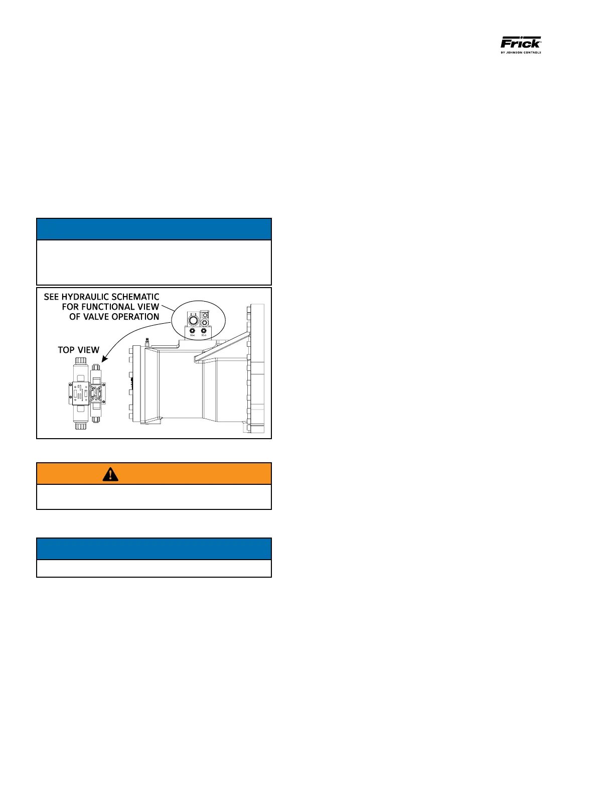
Booster Compressor Loading: The compressor loads when
MSV solenoid YY2 is energized and oil ows from the oil
manifold through valve ports P and B to cylinder port SC2
and enters the load side of the cylinder. Simultaneously, oil
con tained in the unload side of the cylinder ows out cylinder
port SC1 through valve ports A and T to com pressor suction.
Booster Compressor Unloading: The compressor un loads
when MSV solenoid YY1 is energized and oil ows from the
oil manifold through valve ports P and A to cylinder port SC1
and enters the unload side of the cylinder. Simultaneous ly,
oil contained in the load side of the cylinder ows out of
compressor port SC2 through valve ports B and T to com
pressor suction.
NOTICE
To control the rate of loading and unloading, change
cycle time, proportional band, and dead band setpoints
with Quantum control. If additional control is needed,
throttle SC2 or BP.
Figure 22
WARNING
NEVER open valve BP and valve SC2 at the same time
during compressor operation.
VOLUME RATIO CONTROL
NOTICE
See Figure 23 for port references.
Open valve at SC3
Open valve at T1
Compressor Vi increase: The volume ratio Vi is increased
when MSS solenoid valve YY3 is energized and oil ows from
the oil manifold through valve ports P and A to compres
sor port SC3, enters the increase side of the cylinder and
overcomes the decrease spring tension. Simultaneously, oil
ows from T1 port through valve ports B and T to compres
sor suction. The inboard side of the slide stop piston is at
suction pressure.
Compressor Vi decrease: The volume ratio Vi is decreased
when MSS solenoid valve YY4 is energized and oil ows from
the oil manifold through valve ports P and B to compressor
port T1, enters the decrease side of the cylinder. Simultane
ously, oil ows form SC3 port through valve ports A and T
to compressor suction. On these models, YY4 is energized
which permits oil to vent from port A to T with assistance
from the unloader spring.
TO CONTROL THE RATE OF VI CHANGE, THROTTLE THE
NEEDLE VALVE AT SC3 PORT.
COMPRESSOR OIL COOLING SYSTEMS
The RWH unit can be equipped with one of several systems
for controlling the compressor oil tempera ture. They are
single or dualport liquid injection and thermo syphon, air
cooled or watercooled oil coolers. Each system is autom
ati cally controlled, independent of compressor loading or
unloading.
Oil cooling systems should maintain oil temperature within
the following ranges for R717:
Liquid Injection External*
Oil Cooling Oil Cooling
130 170°F 120 160°F
* Thermosyphon oil cooling (TSOC), aircooled, or water
cooled oil cooling (WCOC).
SINGLE-PORT LIQUID INJECTION
The singleport liquid injection system is desig ned to permit
liquid refrigerant injection into one port on the compressor
at any given moment and operates as outlined.
The liquid injection control valve is enabled by the micro
processor when the temperature sensor, in stalled in the
compressor discharge, exceeds the setpoint. Highpressure
liquid refriger ant is then expanded through the tempera
ture control valve (TCV) and cools the compressor. Refer to
P & I DIAGRAMS section for piping and instrumentation
drawings.
DUAL-PORT LIQUID INJECTION
The dualport liquid injection system is design ed to obtain
the most efcient compressor performance at high and low
compression ratios by permitting injection of liquid refriger ant
into one of two ports optimally located on the com pressor.
This minimizes the performance penalty incurred with liquid
injection oil cooling.
The dualport system contains all the com ponents of the
singleport system with the addition of a directional valve
and operates as follows:
The liquid injection solenoid valve is energized by the
micro processor when the temperature sensor, in stalled in
the oil manifold, exceeds the setpoint. Liquid refrigerant is
then passed through the tempera ture control valve (TCV)
to the directional solenoid valve. Depending on the com
pressor’s operating volume ratio (Vi), the micropro cessor
will select the ow of the liquid refrigerant to the optimum
com pressor port.