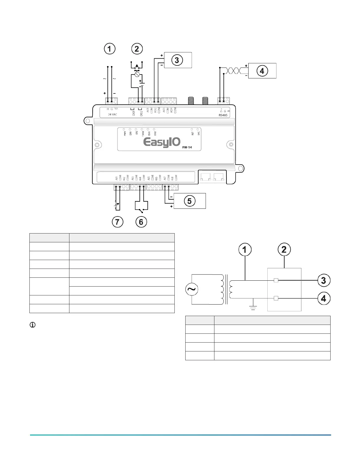
Figure 11: FW-14 wiring diagram
Callout Description
1 Input power
2 General purpose digital output
3 Voltage-controlled actuator
4 Connection to serial devices
Voltage transmitter5
0 V to 10 V or 0 V to 5 V
6 Switch
7 Thermistor, RTD, or potentiometer
Note: If you configure the controller as a
subordinate device and it is at the end of a daisy
chain, install a 120 ohm resistor in parallel with the
RS-485 terminal.
Figure 12: 24 VAC Class 2 transformer power input
Callout Description
1 20 AWG copper stranded wire
2 Controller
3 H terminal
4 G terminal
FW-14 Quick Start Guide 5